Laser oscillator capable of generating light spots in any shape

A laser oscillator, a technology of arbitrary shape, applied in the field of lasers, can solve the problems of laser beam quality degradation, affecting laser efficiency, wavefront distortion, etc., to achieve the effect of reducing diffraction loss, high laser power, and releasing thermal stress

Active Publication Date: 2021-06-08
SHANGHAI INST OF OPTICS & FINE MECHANICS CHINESE ACAD OF SCI
View PDF12 Cites 0 Cited by
  • Summary
  • Abstract
  • Description
  • Claims
  • Application Information

AI Technical Summary

Problems solved by technology

[0002] At present, spot lasers with arbitrary shapes are generally produced by end mirror coating or intracavity / extracavity insertion of binary optical elements. Very obvious, such as wavefront distortion, thermal stress, resulting in degradation of laser beam quality, or even stress cracks

Method used


Image

  • Laser oscillator capable of generating light spots in any shape
  • Laser oscillator capable of generating light spots in any shape
  • Laser oscillator capable of generating light spots in any shape

Examples


Embodiment 1

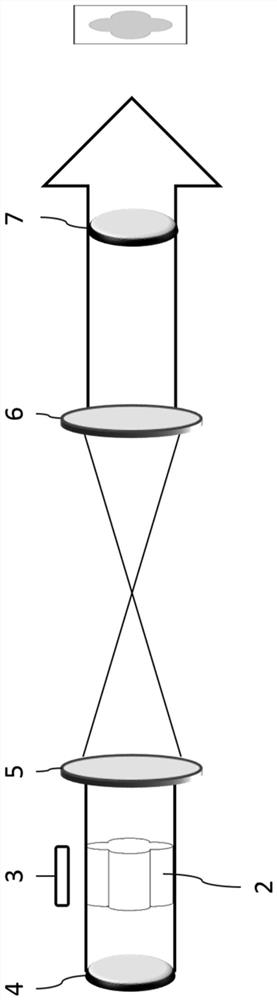
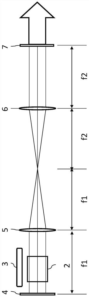
[0036] This embodiment is a laser oscillator of a 4F imaging resonator, such as figure 2 shown. The resonant cavity 1 of the imaging structure is composed of a total reflection mirror, an output mirror and a lens, wherein the object plane is a total reflection mirror, the image plane is an output mirror, and two lenses are used as frequency domain conversion elements. image 3 It is the anisotropic gain medium selected in this embodiment, with holes in the middle area. Although the center (or other places) of the shaped gain medium is empty, in the 4F imaging resonator, the gain medium is located between the lens and the object plane, so the shape of the gain medium can be imaged in the imaging plane, so the shape of the gain medium can be Determines the shape of the output spot. The higher the cutoff frequency of the 4F imaging system, the more high-order modes it can accommodate. The loss of high-order modes and low-order modes is determined by the structure of the imagin...

Embodiment 2

[0042] Figure 10 It is a schematic diagram of an embodiment in which a binary optical element 1 ( 8 ) and a binary optical element 2 ( 9 ) are used to replace ordinary lenses. The binary optical lens has the same Fourier transformation effect as the traditional lens, and can completely replace the traditional lens, and perform frequency conversion to form a frequency domain surface. If there are others that can replace the lens to generate the frequency domain surface, it is also included in the scope of the patent claims.

Embodiment 3

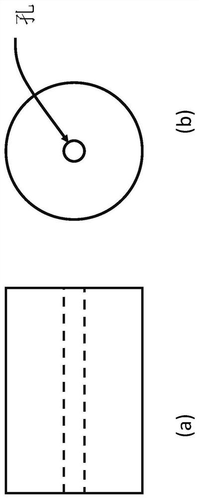
[0044] Such as Figure 11 As shown, on the basis of Embodiment 1, a filter hole is added on the frequency spectrum for mode limiting, and the shape of the filter hole is circular. The laser spot produced is as Figure 12 As shown, it can be seen that the laser spot has no burrs on the edge of the spot compared to the laser spot without pinholes, indicating that the high-frequency information (the edge of the object) has been filtered by the filter pinhole.


PUM


Abstract

The invention provides a laser oscillator, which adopts an imaging system as a resonant cavity, is combined with a special-shaped gain medium to generate laser spots with any shape similar to that of the laser gain medium, and has the effects of releasing thermal stress, improving laser wavefront, avoiding ghost images and the like. A resonant cavity of an imaging system can reduce the diffraction loss (high-frequency space information loss) of a high-order mode, so that the high-order mode and a low-order mode can form oscillation in the cavity without difference, which is totally different from the mode that only a low-order transverse mode of a traditional laser can oscillate, and therefore, any laser spot similar to the gain medium in shape can be generated according to the shape of the gain medium. The laser with any light spot shape can be used in the field of special laser processing or laser medical treatment and the like.

Description

technical field [0001] The invention relates to the field of lasers, in particular to a laser oscillator for generating light spots of arbitrary shapes. Background technique [0002] At present, spot lasers with arbitrary shapes are generally produced by end mirror coating or intracavity / extracavity insertion of binary optical elements. Very obvious, such as wavefront distortion, thermal stress, resulting in degradation of the laser beam quality, or even stress cracks. Contents of the invention [0003] Based on the above-mentioned shortcomings of conventional lasers that generate laser spots of arbitrary shape, the present invention proposes a laser oscillator for generating light spots of arbitrary shape, which adopts a laser resonant cavity with an imaging structure and a special-shaped gain medium. Due to the severe diffraction loss of traditional lasers, only low-order transverse modes can oscillate, and the positions of low-order transverse modes are more concentrat...

Claims


Application Information

Patent Timeline
Patent Type & Authority Applications(China)
IPC IPC(8): H01S3/08H01S3/081
CPCH01S3/0813H01S3/08059
Inventor 张笑琪张海青朱健强张艳丽张昆鹏张国文
Owner SHANGHAI INST OF OPTICS & FINE MECHANICS CHINESE ACAD OF SCI
Why Eureka
Try Eureka