Device and method for enhancing aeration by utilizing hydraulic shearing and gas buoyancy

A hydraulic shearing and aeration technology, applied in chemical instruments and methods, water aeration, biological treatment devices, etc., can solve problems such as easy blockage of aeration system, low oxygenation efficiency, uneven aeration, etc., and achieve Accelerated oxygen transfer rate, long service life, and increased turbulence

Active Publication Date: 2021-06-11
EAST CHINA UNIV OF SCI & TECH
View PDF5 Cites 0 Cited by
  • Summary
  • Abstract
  • Description
  • Claims
  • Application Information

AI Technical Summary

Problems solved by technology

[0007] Aiming at the deficiencies of the prior art, the present invention provides a device and method for enhancing aeration by using hydraulic shearing and gas buoyancy to solve the problem that the aeration system in the prior art is easy to block, easy to damage, large pressure drop, oxygen-filled Problems and technical defects such as low efficiency, uneven aeration, poor mixing effect, etc.

Method used


Image

  • Device and method for enhancing aeration by utilizing hydraulic shearing and gas buoyancy
  • Device and method for enhancing aeration by utilizing hydraulic shearing and gas buoyancy
  • Device and method for enhancing aeration by utilizing hydraulic shearing and gas buoyancy

Examples


Embodiment 1

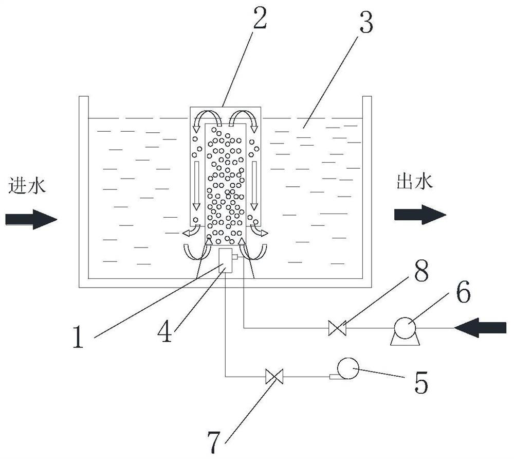
[0050] figure 1 It is the device of the present invention that uses hydraulic shear and gas buoyancy to generate fine bubbles to enhance aeration, and the device for enhancing aeration includes a bubble generating unit 1 and an airlift circulation unit 2 installed above the bubble generating unit 1, The bubble generation unit 1 includes an aeration core tube 4 arranged at the bottom of the aeration tank 3 and a blower 5 and a booster pump 6 that are connected to the aeration core tube 4 through pipelines and placed outside the aeration tank 3 .

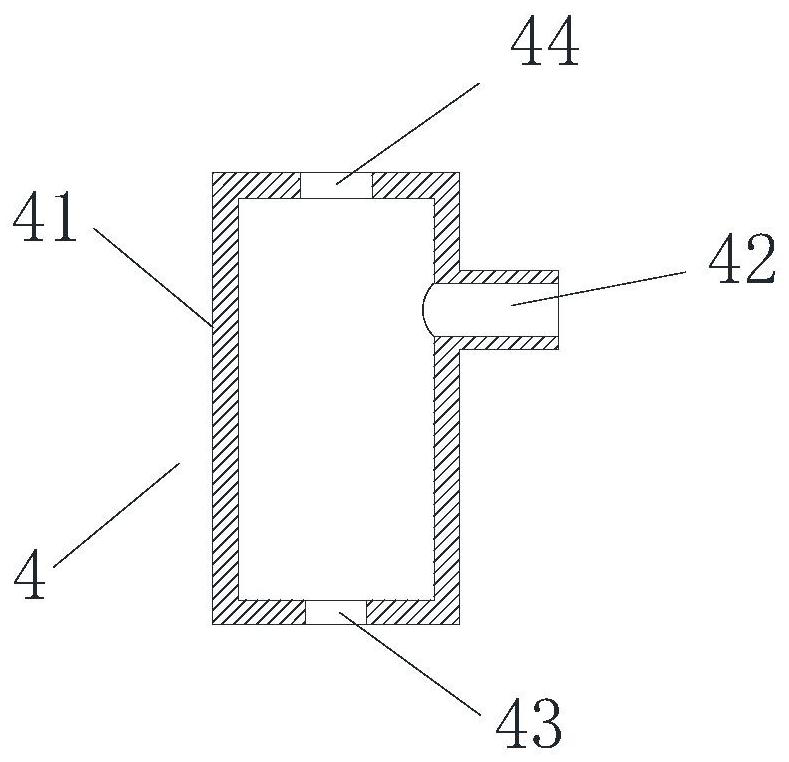
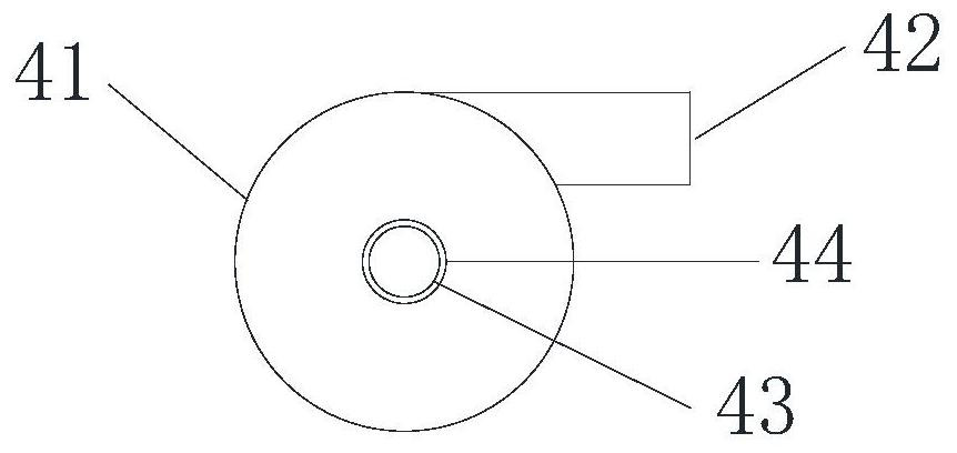
[0051] Wherein, the aeration core tube 4 is located at the center of the bottom of the airlift circulation unit 2, such as figure 2 and 3 As shown, the aeration core tube 4 includes a cylindrical swirl chamber segment 41, the interior of the swirl chamber segment 41 is a cavity structure, the side wall of the swirl chamber segment 41 is provided with a liquid inlet 42, and The direction of the liquid inlet 42 is tangent to the sid...

Embodiment 2

[0075] The device described in Example 1 is used to enhance aeration by utilizing hydraulic shear and gas buoyancy to generate fine bubbles, and transform the traditional blower aeration device. Such as Figure 6 and 7As shown, the width of the aeration tank 3 is 10m, the water depth is 5-6m, and the water flow direction is from left to right. Considering the reconstruction cost, energy consumption and hydraulic retention time, the original aeration head 11 in the first half of the aeration tank 3 is modified, and the original aeration head 11 is used in the second half.

[0076] According to calculations, the aeration-intensifying devices composed of the bubble generation unit 1 and the airlift circulation unit 2 are arranged in 5 rows along the width direction of the aeration tank 3, and each row is arranged with 4 pieces. The gap width between the adjacent airlift circulation units 2 is 1.5-2m, and the distance between the outermost airlift circulation unit 2 and the pool...

Embodiment 3

[0080] Adopt the device described in embodiment 1 to utilize hydraulic shearing and gas buoyancy to produce fine bubbles to strengthen aeration, such as Figure 8 As shown, the width of the aeration tank 3 is 10m, the length is 11m, and the water depth is 5-6m. In the aeration tank 3, four partition walls 9 are sequentially arranged along the length direction, and one end of the partition wall 9 It is connected to the inner wall on one side in the length direction of the aeration tank, and the other end is separated from the inner wall on the other side in the length direction of the aeration tank by 2m. The partition walls 9 are arranged crosswise to form a serpentine flow channel. The partition wall 9 divides the aeration tank 3 into five flow channels 10, the width of the first four flow channels 10 is 2m, and the width of the fifth flow channel 10 is 2.5m.

[0081] The device for enhancing aeration composed of the bubble generating unit 1 and the airlift circulation unit 2...


PUM

PropertyMeasurementUnit
diameteraaaaaaaaaa
heightaaaaaaaaaa
heightaaaaaaaaaa

Abstract

The invention provides a device for enhancing aeration by using hydraulic shearing and gas buoyancy. The device comprises a bubble generation unit and an air lift circulation unit, the bubble generation unit comprises an aeration core tube, an air blower and a booster pump; the aeration core pipe comprises a rotational flow cavity section with a cavity structure inside, and is provided with a liquid inlet, an air inlet and a bubble outlet; the airlift circulation unit comprises an inner circulation area and an outer circulation area. Liquid enters the aeration core pipe in the tangential direction to do high-speed rotational flow motion, gas enters from the bottom and is subjected to directional momentum shearing by the fluid to generate fine bubble groups, the fine bubble groups rise along with mixed liquid in the inner circulation area under the action of gas buoyancy, the mixed liquid in the outer circulation area drops under the action of density difference, and part of the mixed liquid in the aeration tank is sucked by the inner circulation area to form liquid-phase circulation enhanced aeration. According to the invention, the turbulence degree in the aeration tank can be increased, the sludge suspension is maintained, the oxygen is quickly filled, the dissolved oxygen in the aeration tank is uniformly distributed, and the problems of blockage, damage and the like of the aeration device are avoided.

Description

technical field [0001] The invention belongs to the field of wastewater treatment, and in particular relates to a device and method for enhancing aeration by utilizing hydraulic shear and gas buoyancy. Background technique [0002] Biological wastewater treatment is a method of using microbial metabolism to decompose degradable organic matter in wastewater, thereby purifying water. Due to its advantages of large processing capacity, small investment, and economical reliability, it is currently the most common water treatment method. Among them, the treatment effect of the widely used aerobic biological method is often restricted by the aeration performance in the aeration tank. The main parameters of the aeration performance include the energy consumption of the aeration equipment, oxygenation capacity, oxygen utilization rate and sludge suspension. degree etc. In the current process of aerobic biological treatment of sewage, the energy consumption of aeration equipment is ...

Claims


Application Information

Patent Timeline
Patent Type & Authority Applications(China)
IPC IPC(8): C02F3/12C02F7/00C02F1/24
CPCC02F3/1284C02F7/00C02F1/24C02F2201/002C02F2201/005C02F2203/006C02F2209/22Y02W10/10
Inventor 杨强王威许萧刘懿谦陈正军
Owner EAST CHINA UNIV OF SCI & TECH
Why Eureka
Try Eureka