Tumbler type vehicle-mounted flywheel energy storage device with five-degree-of-freedom suspension support

A flywheel energy storage, degree of freedom technology, applied in electromechanical devices, control mechanical energy, electrical components and other directions, can solve the problems of increased system eddy current loss, embedded stress concentration in the flywheel, low economy, etc., to improve energy storage and specific energy. , the effect of reducing the axial length and improving the integration

Active Publication Date: 2021-06-11
JIANGSU UNIV
View PDF3 Cites 3 Cited by
  • Summary
  • Abstract
  • Description
  • Claims
  • Application Information

AI Technical Summary

Problems solved by technology

However, although the topology design scheme of this device uses the idea of ​​"embedding" to reduce the axial volume of the flywheel energy storage device and has a high degree of integration, the embedded part of the magnetic bearing not only makes the processing of the flywheel rotor difficult and the maintenance cost is high. More importantly, it will lead to stress concentration in the embedded part of the flywheel, so the energy storage characteristics and safety characteristics cannot be guaranteed
Furthermore, the metal flywheel in the device is designed in the form of a cylindrical disc, which has low system economy and poor self-stabilization effect under the condition of achieving a specific energy storage. Has a stronger gyroscopic effect, which in turn increases the difficulty of its control
In addition, in order to offset the weight of the flywheel, the axial magnetic bearing of the device adopts a double permanent magnet ring structure, which will inevitably generate magnetic flux leakage and increase the energy consumption of the system, and there is no magnetic circuit coupling between the entire five-degree-of-freedom magnetic bearings. The magnetic isolation aluminum ring replaces the air gap magnetic barrier. Although it can achieve the desired effect, it will increase the eddy current loss of the system at the same time.

Method used


Image

  • Tumbler type vehicle-mounted flywheel energy storage device with five-degree-of-freedom suspension support
  • Tumbler type vehicle-mounted flywheel energy storage device with five-degree-of-freedom suspension support
  • Tumbler type vehicle-mounted flywheel energy storage device with five-degree-of-freedom suspension support

Examples


Embodiment Construction

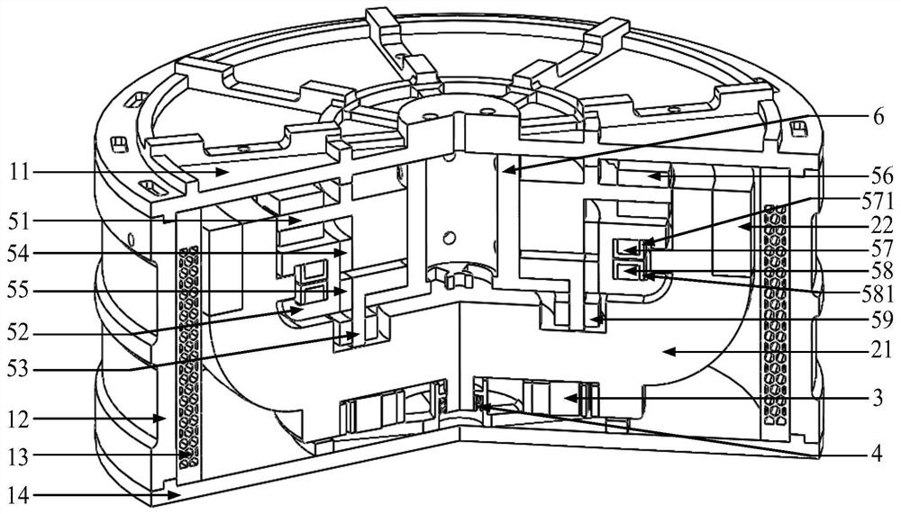
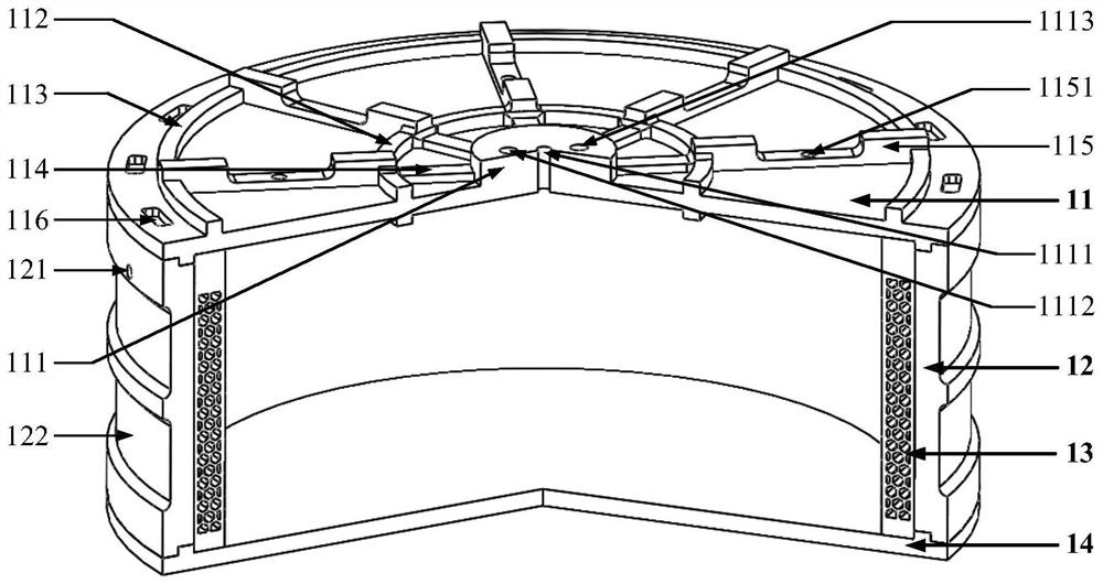
[0036] Such as figure 1 As shown, the outermost part of the present invention is a shell cavity of a vacuum environment, which is composed of an upper end cover 11 of the shell, an outer shell wall 12 of the shell, a honeycomb cover 13 of the inner layer of the shell and a lower end cover 14 of the shell, and the outer shell wall of the shell The upper and lower end surfaces of 12 are respectively closely fitted and fixedly connected with the upper end cover 11 of the housing and the lower end cover 14 of the housing through the grooves provided on the upper and lower ends. The lower end cover 14 is designed as a solid disk. Inside the casing cavity, the supporting frame 6, the drive motor 3, the flywheel, and the inner stator, coil and permanent magnet of the five-degree-of-freedom magnetic bearing are arranged concentrically. The upper end of the support frame 6 is fixedly connected to the casing cavity, and is fixedly sleeved in the inner stator for supporting the inner st...


PUM


Abstract

The invention discloses a tumbler type vehicle-mounted flywheel energy storage device for five-degree-of-freedom suspension support of an electric automobile. A flywheel is in a bowl shape formed by interference fit of a metal flywheel rotor and a composite material ring, the metal flywheel rotor is composed of an upper section ring, a middle section hollow hemisphere and a lower section ring, the composite material ring tightly sleeves the upper section ring to form a bowl-shaped bowl opening part, the inner wall of the bottom end of the upper section ring protrudes inwards in the radial direction to form a ring-shaped axial thrust disc, the upper region of the axial thrust disc is a bowl opening empty groove layer, and the lower region of the axial thrust disc is sequentially provided with a spherical empty groove layer and a bowl bottom empty groove layer to form a flywheel inner cavity, a supporting frame is sleeved in an inner stator, a bowl foot ring cavity is formed betweenthe lower section ring and a bowl foot central shaft in the middle of the lower section ring, and a driving motor is accommodated in the bowl foot ring cavity. A magnetic bearing and the motor are arranged in the flywheel, the axial length of the device is effectively reduced, the integration level is improved, the flywheel is in a shape with the light upper portion and the heavy lower portion, the gravity center is concentrated at the bowl bottom, and natural self-balance is achieved.

Description

technical field [0001] The invention relates to the field of a vehicle-mounted flywheel energy storage device (also called a flywheel battery) for an electric vehicle, in particular to a vehicle-mounted energy storage device with a five-degree-of-freedom suspension support. Background technique [0002] As a green energy storage device developed in recent years, the flywheel energy storage device has the advantages of high specific power, high charge and discharge efficiency, low noise pollution and long life cycle. It is one of the ideal power batteries for electric vehicles. However, the main challenges currently restricting the development of flywheel energy storage devices for electric vehicles are technical problems such as large space occupation, unreliable performance, high cost, difficulty in ensuring safety performance, and complex control methods. [0003] In terms of space arrangement: the topology of the traditional flywheel energy storage device is generally arr...

Claims


Application Information

Patent Timeline
Patent Type & Authority Applications(China)
IPC IPC(8): H02K7/02
CPCH02K7/025Y02E60/16
Inventor 张维煜张林东朱熀秋单龙俞珏鑫王健萍
Owner JIANGSU UNIV
Why Eureka
Try Eureka