Combined cavity for flow field video and aerodynamic load measurement

An aerodynamic load, combined technology, applied in the cross field, can solve the problem of increasing the workload of wind tunnel test, video measurement of difficult flow field structure, static pressure distribution of aerodynamic characteristics, noise load and vibration response, cavity model processing cost increase, etc. problems, to avoid processing multiple sets of models, convenient disassembly and assembly, and saving raw materials

Active Publication Date: 2021-06-18
INST OF HIGH SPEED AERODYNAMICS OF CHINA AERODYNAMICS RES & DEV CENT
View PDF10 Cites 2 Cited by
  • Summary
  • Abstract
  • Description
  • Claims
  • Application Information

AI Technical Summary

Problems solved by technology

[0004] However, it can be seen from many existing examples at home and abroad that the research process for specific problems often includes a variety of test types, but the design and processing of the above three cavity models are relatively independent of each other, requiring multiple sets of tests Models can complete all the test content to obtain aerodynamic load data, resulting in a significant increase in the cost of cavity model processing
At the same time, for different test types, it is necessary to disassemble the test device and frequently replace the cavity model, which significantly increases the workload of the wind tunnel test; the most critical thing is that it is difficult to simultaneously integrate and obtain the flow field structure of the cavity structure Video measurements, aerodynamic properties, static pressure distribution, noise loading and vibration response

Method used


Image

  • Combined cavity for flow field video and aerodynamic load measurement
  • Combined cavity for flow field video and aerodynamic load measurement
  • Combined cavity for flow field video and aerodynamic load measurement

Examples


Embodiment 1

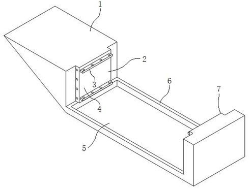
[0035] When the substrate 1 is only connected with rigid functional boards 12 on both sides of the first connecting part 2 and the second connecting part 7, the whole constructed cavity can be used for unsteady pulsating pressure measurement or oil flow test on the cavity wall surface.

Embodiment 2

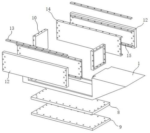
[0037] When the elastic plate 14 is combined and connected to the inner wall of the functional plate 12, the entire constructed cavity can be used to study the mutual coupling characteristics of the elastic cavity wall and the noise in the cavity

Embodiment 3

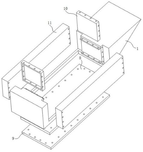
[0039] like image 3 As shown, when the functional plate 12 and the elastic plate 14 are replaced by a transparent plexiglass plate 11, the entire constructed cavity can be used to display and measure the flow structure, so that the device can be applied to PIV test, schlieren test and video measurement test etc.

[0040] The research contents of the above-mentioned embodiments have a wide range of application, and can be simultaneously applied to cavity unsteady pulsation pressure measurement test, flow display test, acoustic-vibration characteristic research and so on.


PUM


Abstract

The invention discloses a combined cavity for flow field video and aerodynamic load measurement, which comprises a base body, the base body comprises a front end, a rear end and a frame beam, the front end and the rear end are of an integrated structure, the frame beam is connected with the front end and the rear end, a cavity structure is formed among the front end, the rear end and the frame beam, protruding connecting parts are arranged at the front end and the rear end, a functional plate is arranged on the frame beam between the front end and the rear end, the functional plate is movably connected with the side edges of the connecting parts, a bottom plate is arranged in the frame beam, and the bottom plate is movably connected with the connecting parts. The combined cavity can be applied to cavity unsteady pulsating pressure measurement tests, flow display tests, acoustic vibration load characteristic research and the like at the same time; and the parts are simple in combination mode and convenient to disassemble and assemble, the test process is simplified, the period is shortened, and the test efficiency is improved.

Description

technical field [0001] The invention relates to the interdisciplinary technical field of experimental fluid mechanics, aerodynamics, etc., and specifically relates to a combined chamber for flow field video and aerodynamic load measurement. Background technique [0002] Due to its special structural form and characteristics, the cavity structure is a typical structure that commonly exists in the aerospace and navigation fields and industrial equipment. It is mainly used for articles, combat weapons, power fuel storage, and landing gear storage. It usually has It has the characteristics of many geometric parameters, complex structure, unconventional configuration and harsh working environment. However, the cavity in the wind tunnel test is different from the structure of the simple equipment on the ground. Because of the complexity of the high-speed flow around the structure, the aerodynamic load on the cavity structure is complicated, and the external flow Sensitive to the ...

Claims


Application Information

Patent Timeline
Patent Type & Authority Applications(China)
IPC IPC(8): G01M9/06G01M9/04G01M10/00
CPCG01M9/04G01M9/06G01M10/00
Inventor 杨党国路波吴军强王显圣周方奇刘刚刘俊郑晓东宁荣辉
Owner INST OF HIGH SPEED AERODYNAMICS OF CHINA AERODYNAMICS RES & DEV CENT
Why Eureka
Try Eureka