Low-temperature composite heat insulation layer, preparation method thereof and application of low-temperature composite heat insulation layer in vehicle-mounted low-temperature hydrogen storage tank

A thermal insulation layer, multi-layer thermal insulation technology, applied in applications, fixed-capacity gas storage tanks, chemical instruments and methods, etc., can solve problems such as difficulty in ensuring safety, and achieve the purpose of extending service time, reducing production costs, and reducing solid heat transfer. Effect

Pending Publication Date: 2021-07-02
TECHNICAL INST OF PHYSICS & CHEMISTRY - CHINESE ACAD OF SCI
View PDF1 Cites 6 Cited by
  • Summary
  • Abstract
  • Description
  • Claims
  • Application Information

AI Technical Summary

Problems solved by technology

[0005] However, for low-temperature hydrogen storage tanks, the insulation performance of the insulation layer at atmospheric pressure is also very important. Once the insulation layer is damaged, such as when a car has a traffic accident or a vacuum valve is damaged, after the air enters the insulation laye

Method used


Image

  • Low-temperature composite heat insulation layer, preparation method thereof and application of low-temperature composite heat insulation layer in vehicle-mounted low-temperature hydrogen storage tank
  • Low-temperature composite heat insulation layer, preparation method thereof and application of low-temperature composite heat insulation layer in vehicle-mounted low-temperature hydrogen storage tank
  • Low-temperature composite heat insulation layer, preparation method thereof and application of low-temperature composite heat insulation layer in vehicle-mounted low-temperature hydrogen storage tank

Examples


preparation example Construction

[0081] The preparation method of the present invention will be further described in detail in conjunction with specific examples below. It should be understood that the following examples are only for illustrating and explaining the present invention, and should not be construed as limiting the protection scope of the present invention. All technologies realized based on the above contents of the present invention are covered within the scope of protection intended by the present invention.

[0082] The experimental methods used in the following examples are conventional methods unless otherwise specified; the reagents and materials used in the following examples can be obtained from commercial sources unless otherwise specified.

[0083] In the description of the present invention, it should be noted that the terms "first", "second" and so on are only used for descriptive purposes, and do not indicate or imply relative importance.

[0084] The hollow glass microspheres used ...

Embodiment 1

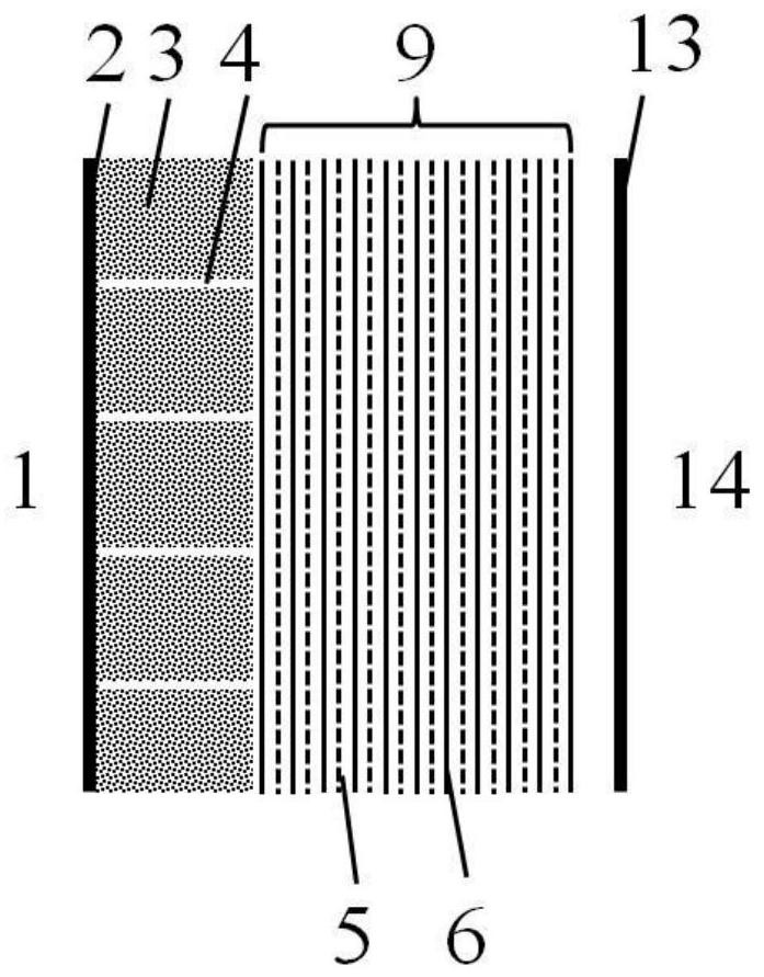
[0087] The thermal insulation structure of the composite thermal insulation layer of this embodiment is as follows: figure 1 As shown, the composite thermal insulation layer of this embodiment is applied to a vehicle-mounted liquid hydrogen (20K) storage tank, and the ambient temperature of the storage tank is 300K, so the temperature at both ends of the composite thermal insulation layer is 20K-300K.

[0088] The vehicle-mounted liquid hydrogen storage tank is a cylindrical storage tank with ellipsoidal heads at both ends. The inner liner of the storage tank stores liquid hydrogen, and the outer shell is a vacuum cover. A composite insulation layer is formed between the inner liner and the outer shell. There are lines that bring hydrogen gas into the combustion chamber of the car engine. In the composite heat insulation layer, a composite heat insulation layer of a 10mm thick hollow microsphere layer and 30 layers of uniform density multilayer heat insulation layers is prepar...

Embodiment 2

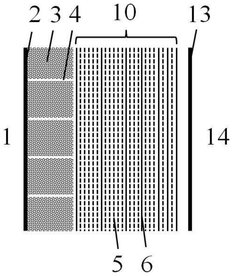
[0107] The thermal insulation structure of the composite thermal insulation layer of this embodiment is as follows: figure 2 As shown, the composite thermal insulation layer of this embodiment is applied to a vehicle-mounted liquid hydrogen (40K) storage tank, and the ambient temperature of the storage tank is 300K, so the temperature at both ends of the composite thermal insulation layer is 40K-300K.

[0108] The vehicle-mounted hydrogen storage tank is the same as in Example 1, except that in the composite insulation layer, a composite insulation layer with a thickness of 20 mm of hollow microsphere layers and 30 layers of variable-density multilayer insulation layers is prepared. The preparation method is as follows:

[0109] 1. Preparation of hollow microsphere layer:

[0110] 1) The hollow microsphere powder is made of hollow glass microspheres, and the density of the hollow glass microspheres is 0.25g / cm 3 , the compressive strength is 5.2MPa, the particle size is 20-8...


PUM

PropertyMeasurementUnit
Thicknessaaaaaaaaaa
Thicknessaaaaaaaaaa
Thicknessaaaaaaaaaa

Abstract

The invention provides a low-temperature composite heat insulation layer, a preparation method thereof and application of the low-temperature composite heat insulation layer in a vehicle-mounted low-temperature hydrogen storage tank. The composite heat insulation layer comprises a hollow microsphere layer and a multi-layer heat insulation layer; the hollow microsphere layer comprises a support body and hollow microsphere powder; the support body is filled with the hollow microsphere powder to form the hollow microsphere layer; and the multi-layer heat insulation layer comprises at least one of a uniform-density multi-layer heat insulation material layer, a variable-density multi-layer heat insulation material layer, a uniform-density integrated heat insulation film and a variable-density integrated heat insulation film. According to the composite heat insulation layer, the hollow microsphere layer and the multi-layer heat insulation layer are used in a composite mode, and the advantages of the two heat insulation layers are exerted. In high vacuum, hollow microspheres in point contact can prolong a solid heat conduction path and reduce solid heat transfer to the maximum extent. The multi-layer heat insulation layer can effectively block radiation heat transfer. The two heat insulation layers are matched to prepare the composite heat insulation layer, and the composite heat insulation layer has more excellent heat insulation performance.

Description

technical field [0001] The invention belongs to the technical field of low-temperature heat insulation, and in particular relates to a composite heat-insulation layer, a preparation method thereof, and an application in a vehicle-mounted low-temperature hydrogen storage tank. Background technique [0002] Hydrogen can be produced from water, and the product of its combustion is water. Therefore, hydrogen energy is a renewable energy and a clean energy. It has a high combustion calorific value, and the heat generated by burning the same mass of hydrogen is about three times that of gasoline. In recent years, with the rapid development of hydrogen energy technology, its application in automobiles has become increasingly mature. The storage of on-board hydrogen energy is crucial, which determines the driving range, safety and cost of the car. The storage of on-board hydrogen energy can be divided into chemical storage, gas compression storage and cryogenic storage. The chem...

Claims


Application Information

Patent Timeline
IPC IPC(8): F17C1/12B32B5/02B32B5/16B32B7/08B32B9/04B32B17/06B32B27/12B32B29/02
CPCB32B5/02B32B5/16B32B7/08B32B9/04B32B17/06B32B27/12B32B29/02B32B2262/0261B32B2262/0276B32B2264/10B32B2264/101B32B2264/107B32B2307/304B32B2439/00F17C1/12F17C2203/03F17C2203/0308F17C2203/0329F17C2203/0337Y02E60/32
Inventor 王平严开祺张敬杰
Owner TECHNICAL INST OF PHYSICS & CHEMISTRY - CHINESE ACAD OF SCI
Why Eureka
Try Eureka