
Copper wire machining annealing machine

A technology for processing annealing and copper wire, applied in the field of technical processing, can solve the problems of coarse crystal structure of copper wire, damage to ductility and conductivity of copper wire, and short fatigue life.

Inactive Publication Date: 2021-07-06
储继鹏
View PDF0 Cites 0 Cited by
  • Summary
  • Abstract
  • Description
  • Claims
  • Application Information

AI Technical Summary

Problems solved by technology

[0003] First of all, after the copper wire enters the annealing machine, due to the temperature rise, it is necessary to pass a protective gas around the copper wire to prevent the surrounding air from reacting with the copper wire when the copper wire is heated, so that the copper wire is oxidized into copper oxide, so that The ductility and conductivity of the copper wire are damaged, and when the protective gas is passed through, because the copper wire is heated and softened, the position where the surface of the copper wire is impacted by the protective gas is easily bent by force, causing the copper wire to deform
[0004] Secondly, because the copper wire needs to be cooled after annealing, many copper wires are prepared by natural cooling of the copper wire, and the natural cooling is easy to oxidize the copper wire due to contact with the outside air, and the natural cooling time is short, and the copper wire The annealing efficiency is improved, but due to the short cooling time, the copper wire structure is coarse, the toughness and plasticity are reduced, and the fatigue life is short

Method used


Image

  • Copper wire machining annealing machine
  • Copper wire machining annealing machine
  • Copper wire machining annealing machine

Examples


Embodiment Construction

[0020] The following will clearly and completely describe the technical solutions in the embodiments of the present invention with reference to the accompanying drawings in the embodiments of the present invention. Obviously, the described embodiments are only some, not all, embodiments of the present invention. Based on the embodiments of the present invention, all other embodiments obtained by persons of ordinary skill in the art without making creative efforts belong to the protection scope of the present invention.

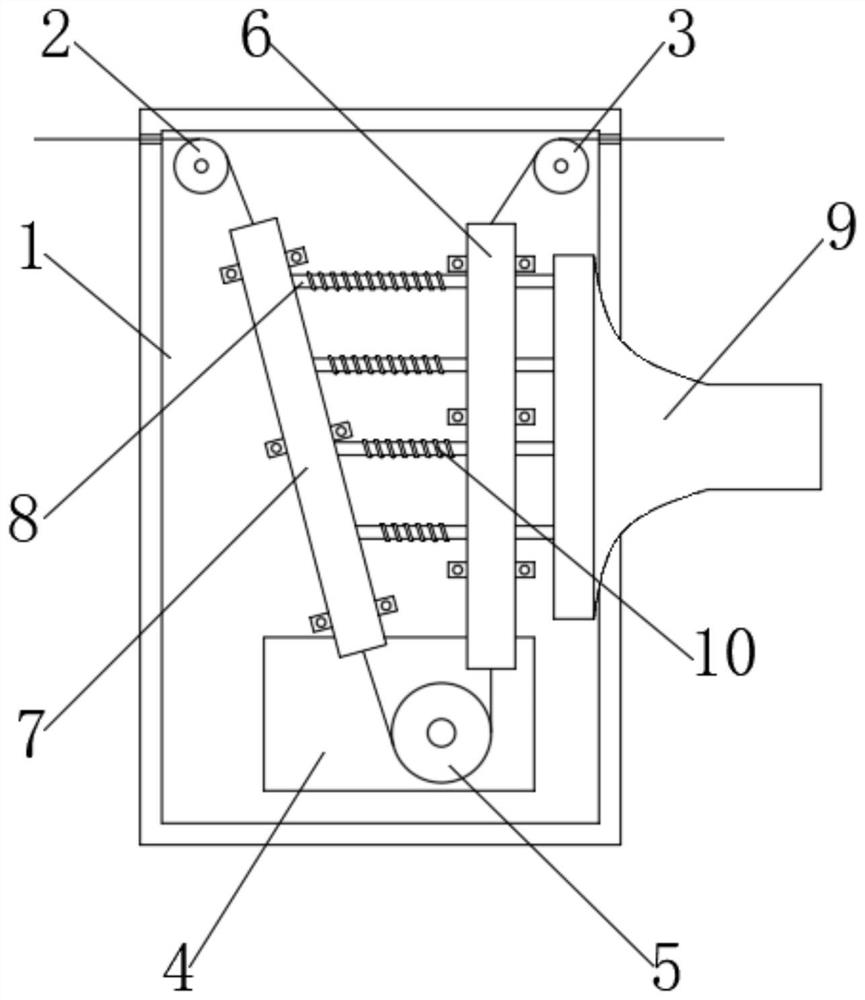
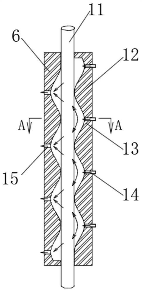
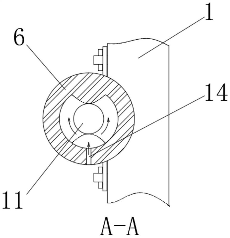
[0021] see Figure 1-4 , a copper wire processing annealing machine, including a casing 1, a guide wheel 2 is movably installed on one side of the top of the casing 1, and a guide wheel 3 is movably installed on the other side of the top of the casing 1, and the guide wheel 2 and the connecting wheel are movably installed. The electric guide wheels 3 all play a guiding role. The copper wire 11 enters the inside of the casing 1 from the place connected to the e...


PUM


Abstract

The invention relates to the technical field of metal machining, and discloses a copper wire machining annealing machine which comprises a machine shell. A guide wheel is movably installed on one side of the top of the interior of the machine shell, a power connection guide wheel is movably installed on the other side of the top of the machine shell, and a heat preservation device is fixedly installed at the lower end of the interior of the machine shell. An electrifying wheel is movably mounted in the heat preservation device, an annealing tank located between the power connection guide wheel and the electrifying wheel is fixedly mounted on the front face of the machine shell, convex peaks and concave valleys on one side of the interior of the annealing tank are arranged at intervals, and the two sides of the interior of the annealing tank are arranged in parallel. According to the copper wire machining annealing machine, due to the wavy design in the annealing tank, when nitrogen is blown out of a gas inlet pipe and impacts a copper wire, the impact position is jacked by the convex peaks on one side of the wavy shape, so that the copper wire is prevented from being impacted and bent, meanwhile, due to the wavy design, the sprayed nitrogen is deflected to the upper side and the lower side, the nitrogen can be gathered around the copper wire, and the oxygen content of gas around the copper wire reaches the minimum.

Description

technical field [0001] The invention relates to the technical field of technical processing, in particular to a copper wire processing annealing machine. Background technique [0002] In order to soften the material or workpiece after casting, forging, welding or cutting, reduce hardness, improve machinability, eliminate residual stress, reduce deformation and crack tendency, it is necessary to slowly heat the metal to a certain temperature and keep it for a sufficient time. Finally, cool down at an appropriate rate. [0003] First of all, after the copper wire enters the annealing machine, due to the temperature rise, it is necessary to pass a protective gas around the copper wire to prevent the surrounding air from reacting with the copper wire when the copper wire is heated, so that the copper wire is oxidized into copper oxide, so that The ductility and conductivity of the copper wire are damaged, and when the protective gas is passed through, because the copper wire is...

Claims


Application Information

Patent Timeline
Patent Type & Authority Applications(China)
IPC IPC(8): C21D9/56C21D1/26C22F1/02C22F1/08
CPCC21D1/26C21D9/561C21D9/562C22F1/02C22F1/08
Inventor 储继鹏
Owner 储继鹏
Learn More