Direct-fired heating device for denitration system

A heating device, direct-fired technology, applied to the combustion of block fuel and liquid fuel, the combustion of block fuel and gaseous fuel, the combustion of block fuel and powder fuel, etc., which can solve the increase of manufacturing cost , poor economy, shortened lifespan, etc.

Pending Publication Date: 2021-07-06
MCC CAPITAL ENGINEERING & RESEARCH
View PDF2 Cites 0 Cited by
  • Summary
  • Abstract
  • Description
  • Claims
  • Application Information

AI Technical Summary

Problems solved by technology

Although blast furnace gas has a low calorific value, because it burns in the adiabatic flue, the temperature of the high-temperature flue gas produced by it can reach 1200-1400 °C, and during the ignition process, if natural gas or oil gun is used to ignite, the combustion temperature will be higher , can reach 1500-1700°C, while the use temperature of ordinary refractory castables is about 1300°C, so it is easy to cause the castables of the ignition air duct to fall off, and then the steel plate of the air duct is deformed by high temperature, and the service life is shortened; if the refractory castable with better performance is used Castables, such as aluminum oxide hollow ball castables, will cause a substantial increase in manufacturing costs because of their high price; in addition, in the prior art, a large excess air coefficient is used to reduce the combustion smoke temperature, but this method will consume a lot of Adding extra air required for heating, which results in more gas being added, making it less economical
[0012] In the prior art, there is a direct-fired temperature rise heating device (CN 209501296 U) for a denitrification system, and a flue gas heating system (CN 210069874 U). In this way, the flame combustion area is relatively fixed, the flue gas heating area is small, and it is impossible to heat the flue with a large cross-section. The temperature in the area closer to the flame area of ​​the direct combustion furnace is higher, and the temperature in the area near the wall around the flue is lower. The mixing effect of axial airflow in the section is poor, which is not conducive to the rapid transfer and uniform distribution of heat

Method used


Image

  • Direct-fired heating device for denitration system
  • Direct-fired heating device for denitration system
  • Direct-fired heating device for denitration system

Examples


Embodiment Construction

[0061] In order to understand the technical features, objects, and effects of the present invention, specific embodiments of the present invention will be described with reference to the drawings.

[0062] DETAILED DESCRIPTION OF THE INVENTION The embodiments of the invention are intended to be construed as limiting the invention. Under the teachings of the present invention, those skilled in the art may be considered based on any possible variation of the present invention, which should be considered as a scope of the invention. It should be noted that when the element is referred to as "set to" another element, it can be directly in another element or may exist in the hidden element. When a component is considered to be "connected" another element, it may be directly connected to another element or may always exist in the center element. The term "installation", "connected", "connection" should be broadly understood, for example, can be mechanically connected or electrically con...


PUM


Abstract

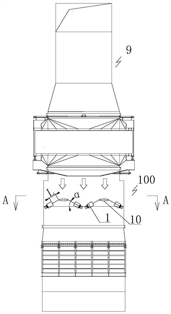
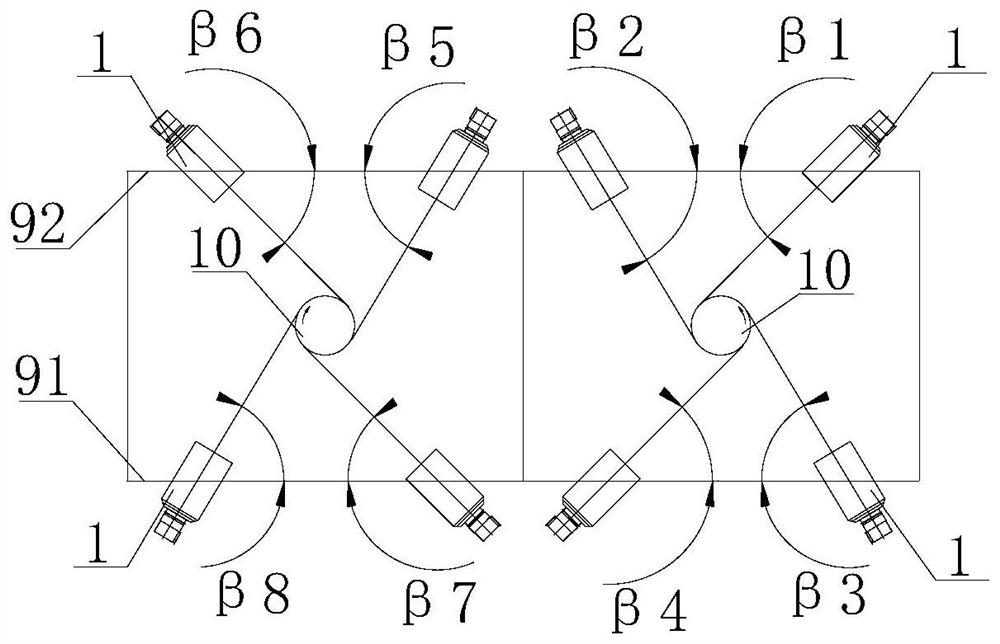
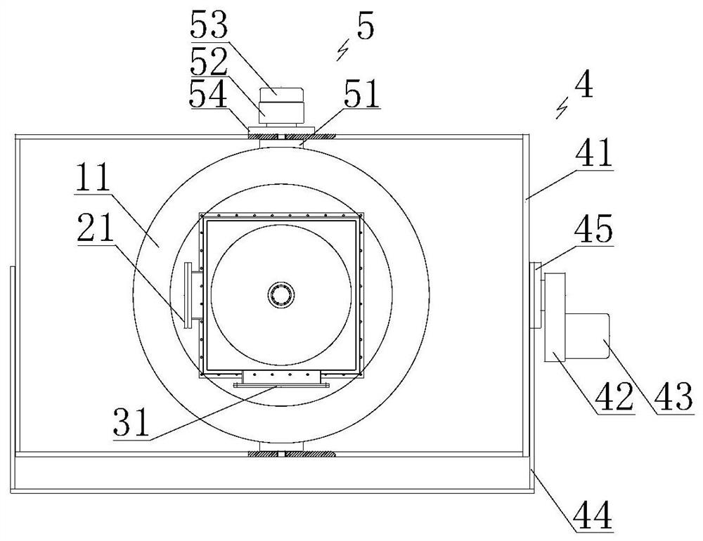
The invention relates to a direct-fired heating device for a denitration system. The direct-fired heating device for the denitration system comprises multiple flame combustors, wherein each flame combustor is used for directly heating and warming flue gas; the multiple flame combustors form at least two combustor groups; the flame stream center line of each flame combustor of each combustor group is tangent to an imaginary tangent circle, and the cut-in directions of the two adjacent combustor groups are opposite; the flame jetting direction of each flame combustor is opposite to the flue gas stream direction, and the flame jetting length can be adjusted; a first adjustable included angle is formed between the central axis of each flame combustor and the horizontal direction; and a second adjustable included angle is formed between the central axis of each flame combustor and the vertical direction. According to the direct-fired heating device for the denitration system provided by the invention, the flue gas is directly heated, the flue gas temperature is promoted to reach the ideal denitration reaction temperature range of the catalyst, the expected denitration reaction is realized, the ultralow emission requirement is met, and the equipment operation economic benefit is improved.

Description

Technical field [0001] The present invention relates to the field of flue gas denitration technology, and more particularly to a straight-blade heating device for a denitrite system. Background technique [0002] Governance of air pollution is an important part of environmental governance. With the improvement of industrial development and living standards, people have become more concerned about environmental issues and corporate environmental issues. [0003] Nitrogen oxides (NOX) are one of the main atmospheric pollutants, one of the main factors of acid rain, photochemical smoke, and PM2.5 pollution. At present, my country's industrial source NOx emissions account for more than 70% of NOx emissions, and the control emission technology of NOx in industrial flue gas mainly includes combustion control technology and combustion control technology. Combustion control technology includes low nitrogen combustion technology, reconstitution technology, and flue gas recirculation techn...

Claims


Application Information

Patent Timeline
Patent Type & Authority Applications(China)
IPC IPC(8): F23J15/08F23C5/08F23C5/02F23D14/04F23D14/64
CPCF23C5/02F23C5/08F23D14/04F23D14/64F23J15/08F23J2215/10
Inventor 耿明山任乐芦良向继涛
Owner MCC CAPITAL ENGINEERING & RESEARCH
Why Eureka
Try Eureka