LLC resonant converter based on switch control inductor and control method
A resonant converter, switching control technology, applied in the direction of regulating electrical variables, control/regulating systems, high-efficiency power electronic conversion, etc., can solve problems such as high cost and difficult physical design, achieve low voltage and current stress, design and testing Ease, the effect of reducing manufacturing costs and time
- Summary
- Abstract
- Description
- Claims
- Application Information
AI Technical Summary
Problems solved by technology
Method used
Image
Examples
Embodiment 1
[0039] Such as Figure 4 As shown, this embodiment provides an LLC resonant converter based on switch-controlled inductors, including an H-bridge inverter, a resonant network, a rectifier network and a low-pass filter network connected in sequence, and the resonant network includes a resonant inductor and a resonant The capacitor also includes a switch control inductor SCI, which is connected in parallel with the resonant inductor. On the premise of keeping the switching frequency constant, the variable reactance control is realized by using the SCI, and the topology of the scheme is simple.
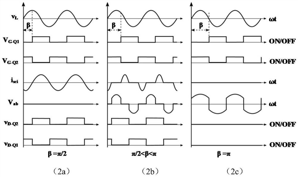
[0040] SCI is a mechanism that uses a semiconductor power switch to control inductive reactance, which can be realized by a linear inductor and a power switch in series. SCI includes serial full-wave SCI and parallel full-wave SCI, such as figure 1 (1a) and (1b) shown. A series-type full-wave SCI consists of two series networks consisting of a switch and a diode connected in anti-paral...
Embodiment 2
[0049] In the LLC resonant converter based on switch-controlled inductors provided by this implementation, in the resonant inductor L a Add a transformer between SCI and SCI, such as Figure 5 shown. The transformer can be used as a resonant inductor L a , the leakage inductance can be used as the SCI inductance L b , and the appropriate switching device can be flexibly selected by adjusting the turn ratio. All the other are with embodiment 1.
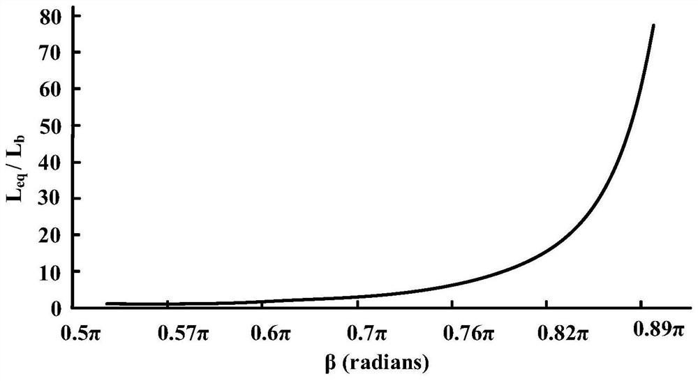
[0050] The equivalent inductance Ls of the resonant inductance of the SCI parallel network and the LLC resonant converter is shown in formula (3):
[0051]
[0052] L eq The value can be determined by formula (2).
[0053] Therefore, the equivalent inductance L s It can be adjusted by changing β. When β=π, L s is the maximum value, equal to L a . When β=π / 2, L s is the minimum value, equal to L a ‖ L b . In fact, to avoid L eq = ∞, the maximum value of β>0.9π is avoided, because L eq The increase of is exponential i...
Embodiment 3
[0080] The converter of this embodiment is applied to a modular power system structure. In a modular power system structure, the configuration of the converter includes input series output series (ISOS), input series output parallel (ISOP), input parallel output series (IPOS) ) and input-parallel-output-series (IPOS) converters. Any of the aforementioned modular structures of the proposed converter scheme can be applied without introducing any complexity.
PUM
 Abstract
Description
Claims
Application Information
 - R&D
- Intellectual Property
- Life Sciences
- Materials
- Tech Scout
- Unparalleled Data Quality
- Higher Quality Content
- 60% Fewer Hallucinations
Browse by: Latest US Patents, China's latest patents, Technical Efficacy Thesaurus, Application Domain, Technology Topic, Popular Technical Reports.
© 2025 PatSnap. All rights reserved.Legal|Privacy policy|Modern Slavery Act Transparency Statement|Sitemap|About US| Contact US: help@patsnap.com


