Hermetia illucens feeding device

A technology of phoenix insects and feeding trays, which is applied in the field of insect breeding equipment, can solve the problems of low automation and high labor intensity, and achieve the effects of high automation, high work efficiency, and improved feeding efficiency

Pending Publication Date: 2021-07-13
青岛得八兄弟机械有限公司
11 Cites 0 Cited by

AI-Extracted Technical Summary

Problems solved by technology

[0003] The invention discloses a feeding device for phoenix worms, which solves the technical problems of low automation and high labor intensity in the prior art of phoenix worm fe...

Method used

As shown in Figure 4, described raising dish 5 comprises bottom wall 54 and four side walls 55, and the first end of described bottom wall 54 is connected with wherein side wall 55 is rotated, and the second of described bottom wall 54 The end is clamped with the opposite side wall 55 . By rotating the bottom wall 54 of the feeding tray 5 relative to the side wall 55, the content in the feeding tray 5 can be driven to include the phoenix worms and drop onto the conveyor belt, wherein the phoenix worms are transported forward by the conveyor belt, the worm skin and the worm skin therein Insect feces can fall to the receiving plate through the filter holes, so that automatic insect extraction and automatic separation of insect skin and insect feces can be realized. The work efficiency is high, and the labor intensity of workers can be greatly reduced. Damage is conducive to ensuring the subsequent commercial use of the phoenix bug.
As shown in Figures 2 and 3, the transfer system 4 includes a transmission mechanism 41 and a transmission drive unit 42 that are located below the lifting sprocket group 25 and correspond to the feeding tray 5 positions, and the transmission mechanism 41 includes a transmission shaft and a conveyor belt sleeved outside the transmission shaft, the transmission drive unit 42 can transmit the rotational motion to the transmission shaft, a fan assembly (not shown) is arranged above the conveyor belt, and an upper conveyor belt and a lower conveyor belt are provided between the conveyor belt There is a material receiving plate (not shown), and several filter holes are arranged on the upper conveyor belt and the lower conveyor belt, and the insect skin and insect excrement can be dropped to the material receiving plate through the filte...

Abstract

The invention discloses a hermetia illucens feeding device which comprises a base, a lifting system and a feeding system; the lifting system comprises a lifting support, a lifting chain wheel set, a lifting chain and a lifting driving unit which are arranged on the base, a plurality of supporting rods are arranged along the peripheral wall of the lifting chain, the parts, extending out of the lifting chain, of the supporting rods are rotationally connected with feeding trays, and the lifting driving unit can transmit the rotary motion to the lifting chain wheel set so as to drive the feeding trays to lift; and the feeding system comprises a storage tank, a feeding pipeline, a valve arranged on the feeding pipeline and a feeding driving unit, the tail end of a feeding branch is closed, a plurality of discharging holes are formed in the positions, corresponding to the feeding trays, of the side wall of the feeding branch, and feed in the storage tank can be conveyed to the feeding trays through the feeding driving unit. The hermetia illucens feeding device has the technical effects of being reasonable in structure, high in automation degree, high in feeding efficiency, good in feeding quality and beneficial to reducing the labor cost of enterprises.

Application Domain

Technology Topic

Animal scienceFeed drive +7

Image

  • Hermetia illucens feeding device
  • Hermetia illucens feeding device
  • Hermetia illucens feeding device

Examples

  • Experimental program(1)

Example Embodiment

[0026] Below in conjunction with accompanying drawing and example, the present invention will be further described:
[0027] The following describes in detail the embodiments of the present invention, examples of which are illustrated in the accompanying drawings, wherein the same or similar reference numerals refer to the same or similar elements or elements having the same or similar functions throughout. The embodiments described below with reference to the accompanying drawings are exemplary, only used to explain the present invention, and should not be construed as a limitation of the present invention.
[0028] In the description of the present invention, it should be noted that the terms "installed", "connected" and "connected" should be understood in a broad sense, unless otherwise expressly specified and limited, for example, it may be a fixed connection or a detachable connection connected, or integrally connected; either directly or indirectly through an intermediary. For those of ordinary skill in the art, the specific meanings of the above terms in the present invention can be understood in specific situations.
[0029] In the description of the present invention, it should be understood that the terms "upper", "lower", "front", "rear", "left", "right", "vertical", "horizontal", "top", The orientation or positional relationship indicated by "bottom", "inner", "outer", etc. is based on the orientation or positional relationship shown in the accompanying drawings, and is only for the convenience of describing the present invention and simplifying the description, rather than indicating or implying the indicated device. Or elements must have a particular orientation, be constructed and operate in a particular orientation, and therefore should not be construed as limiting the invention.
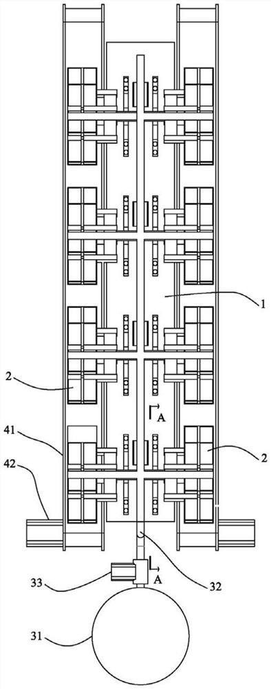
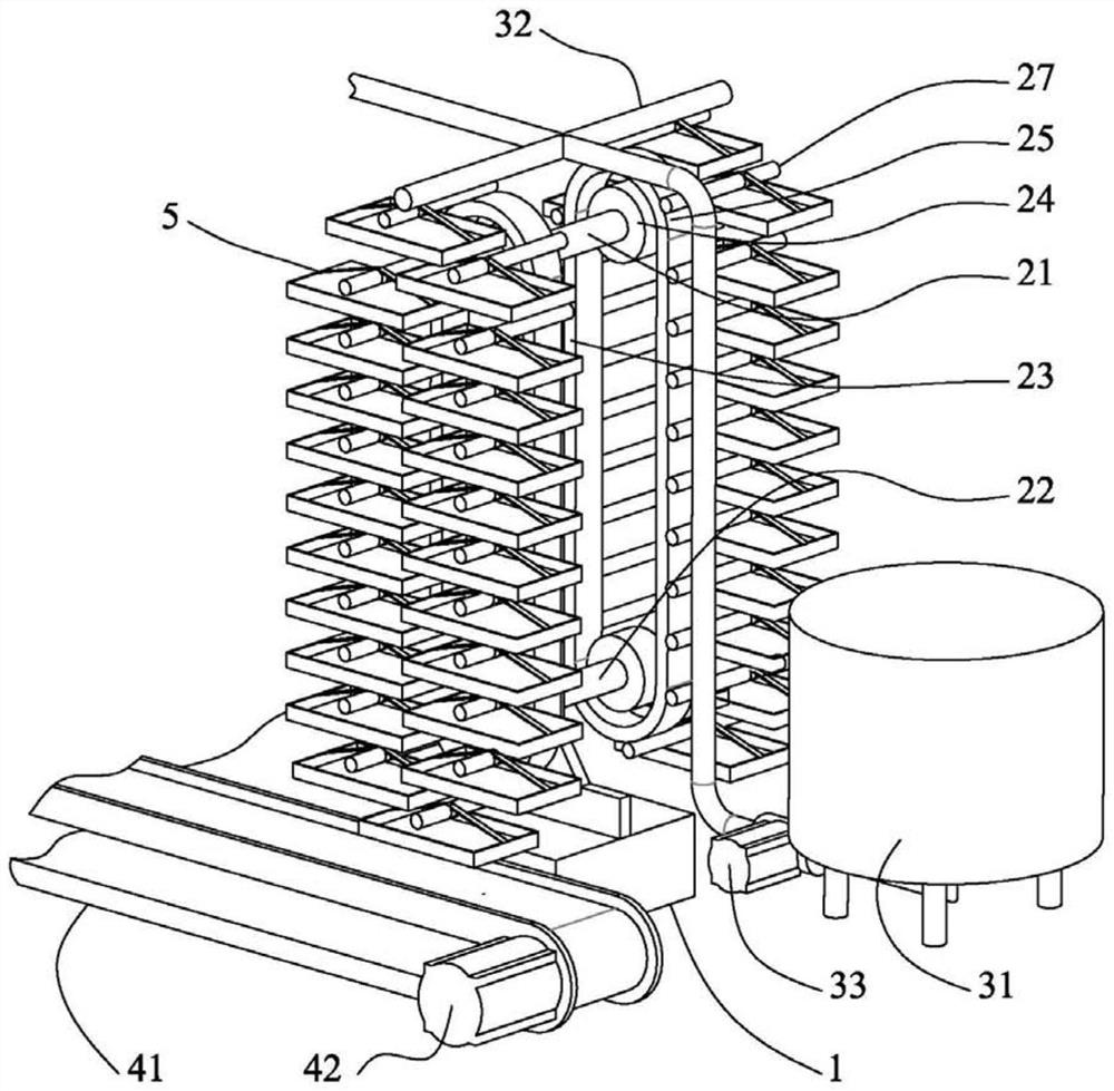
[0030] like Figures 1 to 5 The shown feeding device for phoenix worms includes a base 1, several lifting systems 2, a feeding system 3 and a transfer system 4;
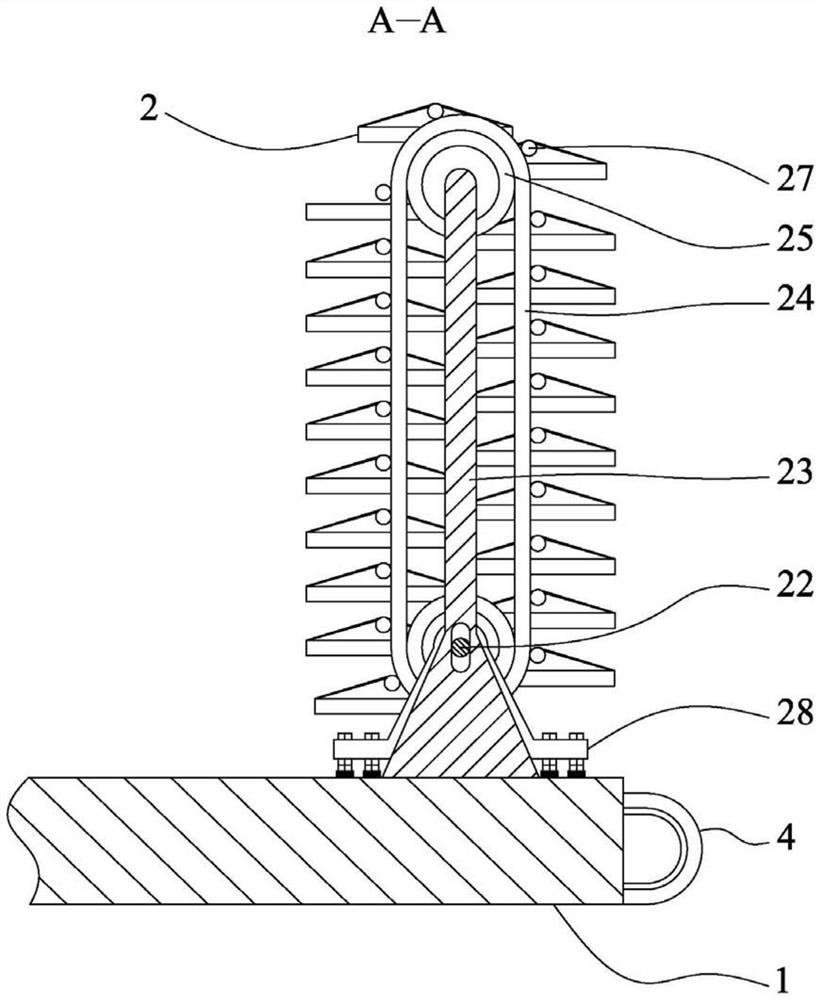
[0031] like figure 2 , 3 As shown, the lifting system 2 includes a lifting bracket, a lifting sprocket set 25 , a lifting chain 24 and a lifting driving unit arranged on the base 1 .
[0032] The lift chain 24 is sleeved outside the lift chain wheel set 25, and a plurality of support rods 27 are arranged along the outer peripheral wall of the lift chain 24. The part of the support rod 27 extending out of the lift chain 24 is rotatably connected to the feeding tray 5. , the elevating drive unit can transmit the rotational motion to the elevating sprocket set 25 to drive the raising and lowering of the feeding tray 5; wherein, the central positions of the opposite sides of the feeding tray 5 are respectively connected with a first broadband 51 and a second broadband 52. The first wide band 51 and the second wide band 52 are connected by a connecting ring 53, and the connecting ring 53 is sleeved outside the support rod 27 and is clearance fit with the support rod 27. The width can be selected in the range of 20-50mm. In actual operation, the speed of the lifting system 2 driving the feeding tray 5 is relatively slow, and generally the contents of the feeding tray 5 are basically laid flat in the feeding tray 5, so the feeding tray 5 is rising and falling. The process is relatively stable. Wherein, in other embodiments of the present invention, a broadband can be connected to the four corners of the feeding tray 5 respectively, and the four broadbands are all connected with the connection ring 53, so that the stability of the feeding tray 5 during the lifting process can be further improved, but this method It can block the feed falling from the feed branch to a certain extent.
[0033]The lift bracket includes a first cross brace 21 , a second cross brace 22 and an upright column 23 . The first cross brace 21 is vertically connected to the upright pillar 23 and is fixed to the base 1 through the upright pillar 23 . The support 22 is parallel to the axis of the first cross support 21 and is fixedly connected to the base 1 through the bearing seat 28 . The bearing seat 28, several nuts and washers are connected to the base 1. By adjusting the number of nuts and washers, the second cross brace 22 can be driven to move up and down to make the lifting chain 24 tension. The two side ends of the first cross brace 21 and the second cross brace 22 are symmetrically provided with a lifting sprocket group 25, a lifting chain 24, a support rod 27 and a number of feeding trays 5, wherein the first cross brace 21 and The same-side ends of the second cross brace 22 are respectively connected with the two sprockets in the lift sprocket group 25 through bearings for rotation, and the second cross brace 22 is provided with a coaxial driven gear outside. The lift drive unit is driven by a motor. The servo motor is fixed on the base 1, and the rotor end of the servo motor is fixed with a driving gear that cooperates with the driven gear. The servo motor can transmit the rotational motion to the second cross support 22, and the second cross support 22 can simultaneously Two sets of lifting sprocket mechanisms are driven to move, which can help to reduce the manufacturing cost of the equipment.
[0034] like figure 2 , 5 As shown, the feeding system 3 includes a storage tank 31, a feeding pipeline 32, a valve provided on the feeding pipeline 32, and a feeding driving unit 33. One end of the feeding pipeline 32 is connected to the storage tank 31, so the The other end of the feeding pipeline 32 is divided into a plurality of feeding branches, the end of the feeding branch is closed, and the side wall of the feeding branch corresponding to the position of the feeding tray 5 is provided with a number of discharge holes 34. The feed in 31 can be transported to the feeding tray 5 via the feeding drive unit 33 . Wherein, the feeding drive unit 33 is a mud pump arranged on the feeding pipeline 32, the end of the feeding branch is closed, and the axis of the discharge hole 34 intersects perpendicularly with the axis of the feeding branch so as to align the feeding tray to the feeding tray. 5 Spray the feed evenly.
[0035] like figure 2 , 3 As shown, the transfer system 4 includes a transmission mechanism 41 and a transmission drive unit 42 that are arranged below the lift sprocket group 25 and correspond to the position of the feeding tray 5. The transmission mechanism 41 includes a transmission shaft and a transmission shaft sleeved outside the transmission shaft. A conveyor belt, the transmission drive unit 42 can transmit the rotational motion to the conveyor shaft, a fan assembly (not shown) is arranged above the conveyor belt, and a feeding plate (not shown) is arranged between the upper and lower conveyor belts of the conveyor belt ), and the upper conveyor belt and the lower conveyor belt are provided with a number of filter holes, and the insect skin and insect excrement can be dropped to the receiving plate through the filter hole under the action of the fan assembly, so that it can assist in the realization of plate separation and automatic cleaning. Insect skin and insect excrement can greatly improve work efficiency and avoid damage to phoenix insects.
[0036] like Figure 4 As shown, the feeding tray 5 includes a bottom wall 54 and four side walls 55, the first end of the bottom wall 54 is rotatably connected with one of the side walls 55, and the second end of the bottom wall 54 is connected with the opposite side wall 55. The side wall 55 is snapped. By rotating the bottom wall 54 of the feeding tray 5 relative to the side wall 55, the contents in the feeding tray 5, including the phoenix worms, can be driven to fall onto the conveyor belt. While the phoenix worms are transported forward by the conveyor belt, the worm skins and The insect excrement can be dropped onto the feeding plate through the filter hole, so that the automatic removal of insects and automatic separation of insect skin and insect excrement can be realized. The work efficiency is high, and the labor intensity of workers can be greatly reduced. The damage is conducive to ensuring the subsequent commercial use of the phoenix worm.
[0037] It also includes a controller, which is electrically connected with the lift drive unit, the feed drive unit 33 , the conveyance drive unit 42 and the fan assembly.
[0038] feeding process
[0039] When feeding is required, the valve on the feeding pipeline 32 is opened, and the lifting and lowering drive unit is driven by the controller to start, and the lifting and driving unit drives the feeding trays 5 on both sides of the lifting bracket to rise and fall, and the controller controls the feeding and driving unit 33 to start. The feed in the storage tank is sprayed from the discharge hole 34 through the feeding pipeline 32 and the feeding branch, and the sprayed feed is fan-shaped and finally falls into the feed tray 5, and when the lifting chain 24 drives the feeding tray 5 to complete one cycle. After the lifting action, the valve on the feeding pipeline 32 is closed, and the controller controls the feeding driving unit 33 to shut down first, and after the set time passes, the controller controls the lifting driving unit to shut down. When it is necessary to divide the phoenix worms or clean the worm skin and worm excrement, the controller controls the lift drive unit, the transmission drive unit 42 and the fan assembly to start up, and the worker opens the bottom wall 54 of each feeding tray 5 in turn. The contents in 5 fall onto the conveyor belt. During the conveying process, the insect skin and insect excrement can be dropped to the receiving plate through the filter hole, and the screened phoenix insects can be collected at the end of the conveyor belt and re-divided. plate.
[0040] The present invention is described above by way of example, but the present invention is not limited to the above-mentioned specific embodiments, and any changes or modifications made based on the present invention belong to the scope of protection of the present invention.

PUM

no PUM

Description & Claims & Application Information

We can also present the details of the Description, Claims and Application information to help users get a comprehensive understanding of the technical details of the patent, such as background art, summary of invention, brief description of drawings, description of embodiments, and other original content. On the other hand, users can also determine the specific scope of protection of the technology through the list of claims; as well as understand the changes in the life cycle of the technology with the presentation of the patent timeline. Login to view more.

Similar technology patents

Filling type pollen feeder

InactiveCN105145411AEasy to operateImprove feeding efficiencyApicultureHoneycombRainy weather
Owner:徐建怀

Classification and recommendation of technical efficacy words

  • Improve feeding efficiency
  • Reduce manual labor intensity

Feeding device for medical accessories

InactiveCN105173627ASpace-saving layoutImprove feeding efficiencyConveyor partsMedical instruments
Owner:MAIDER MEDICAL IND EQUIP

Three-rail vibrating plate

Owner:ACME ELECTRONICS KUNSHAN

Automatic feeding device

ActiveCN104058243ASolve the problem of automatic feedingImprove feeding efficiencyConveyor partsManipulatorEngineering
Owner:SUZHOU LING AUTOMATION EQUIP
Why Eureka
Try Eureka