
Method for degrading phenol by nitrogen-boron co-doped carbon-based microbial fuel cell cathode

A fuel cell cathode and co-doping technology, which is applied in biochemical fuel cells, chemical instruments and methods, biological water/sewage treatment, etc., can solve the problems of ecological environment and human health threats, phenol residue, etc., and achieve improved electrocatalytic performance , excellent stability, easy preparation

Pending Publication Date: 2021-07-16
HEILONGJIANG UNIV
View PDF0 Cites 0 Cited by
  • Summary
  • Abstract
  • Description
  • Claims
  • Application Information

AI Technical Summary

Problems solved by technology

[0004] The purpose of the present invention is to solve the problem that a large amount of phenol in water remains in the environment and pose a serious threat to the ecological environment and human health, and to provide a nitrogen-boron co-doped carbon-based microbial fuel cell cathode with high catalytic activity to degrade The method of phenol in water

Method used


Image

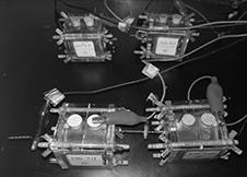
  • Method for degrading phenol by nitrogen-boron co-doped carbon-based microbial fuel cell cathode
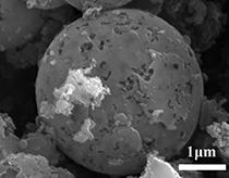
  • Method for degrading phenol by nitrogen-boron co-doped carbon-based microbial fuel cell cathode
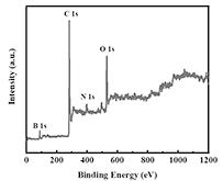
  • Method for degrading phenol by nitrogen-boron co-doped carbon-based microbial fuel cell cathode

Examples


specific Embodiment approach 1

[0021] Specific embodiment one: a kind of nitrogen-boron co-doped carbon-based microbial fuel cell cathode degradation method for phenol in this embodiment is carried out according to the following steps;

[0022] 1. Preparation of BNBC cathode catalyst: 0.299g of CoCl 2 ·6H 2 O, 0.1166g of boric acid and 0.6g of melamine (molar ratio 1:1.5:3) were dissolved in 50mL of deionized water, then 2g of dried pomelo peel powder was added to it, and stirred until completely mixed; the above solution was added Hydrothermally heat at 180° C. for 12 hours in a polytetrafluoroethylene autoclave, and put the hydroheated product in an oven at 60° C. to dry to remove moisture. Subsequently, the obtained solid was transferred to a tube furnace and heated under N 2 Atmosphere, at 2°C min –1 The heating rate was heated from room temperature to 900 °C, and kept at the target temperature for 2 h to obtain a carbonized black product. Immerse the black sample with 0.5M nitric acid and put it in...

specific Embodiment approach 2

[0028] Specific embodiment two: the difference between this embodiment and specific embodiment one is: the CoCl described in step one 2·6H 2 O: The molar ratio of boric acid: melamine is 1:3:3, and the other is the same as the first embodiment.

specific Embodiment approach 3

[0029] Specific embodiment three: the difference between this embodiment and specific embodiment one or two is: the CoCl described in step one 2 ·6H 2 O: The molar ratio of boric acid: melamine is 1:6:3, and the others are the same as the specific embodiment 1 or 2.


PUM


Abstract

The nitrogen-boron co-doped carbon-based catalyst (BNBC) is prepared by utilizing a two-step synthesis method and taking shaddock peel as a carbon source, melamine as a nitrogen source, boric acid as a boron source and CoCl2. 6H2O as a cocatalyst, and the nitrogen-boron co-doped carbon-based catalyst is used as a cathode catalyst of a microbial fuel cell (MFC). Through structural characterization and performance testing, the electricity generation performance of the BNBC cathode MFC and the degradation effect of the BNBC cathode MFC on phenol are obtained. The process comprises the following steps: 1, preparing a BNBC cathode catalyst; 2, preparing a BNBC cathode electrode; 3, assembling a single-chamber MFC reactor; and 4, operation of the MFC reactor and degradation of phenol. Results show that the BNBC cathode MFC has stable power output, and when the initial concentration of phenol is 200mg / L, the degradation rate of phenol wastewater can reach 98.2%, which indicates that the BNBC cathode MFC has an excellent degradation effect on phenol in wastewater while effectively generating electricity. The method is simple in preparation process, low in cost and environment-friendly, has very good degradation efficiency on phenol, and can effectively reduce energy consumption in the phenol wastewater treatment process.

Description

technical field [0001] The invention belongs to the technical field of microbial electrochemistry and wastewater treatment, and in particular relates to a method for degrading phenol at the cathode of a nitrogen-boron co-doped carbon-based microbial fuel cell. Background technique [0002] As the first of the four major pollution sources of water bodies, organic pollutants have been widely valued, among which phenolic substances are a class of organic pollutants with high toxicity. As a typical phenolic refractory substance, phenol is widely used in the production of synthetic resins, spices, dyes, oil refining, pesticides, and pharmaceuticals. When the human body ingests a certain amount of phenol, it will cause acute poisoning, and even inhibit the central nervous system or damage the liver and kidney functions. When the phenol content in water is greater than 5mg / L, aquatic organisms will be poisoned and die. At present, the treatment technologies of phenol wastewater m...

Claims


Application Information

Patent Timeline
IPC IPC(8): C02F3/00C02F3/34H01M8/16C02F101/34
CPCC02F3/005C02F3/34C02F2101/345C02F2305/06H01M8/16Y02E60/50
Inventor 邹金龙邵斯亮代莹
Owner HEILONGJIANG UNIV
Learn More