Disc type permanent magnet synchronous motor, energy storage flywheel and method

A permanent magnet synchronous motor, energy storage flywheel technology, applied to synchronous motors with static armatures and rotating magnets, to control mechanical energy, magnetic circuits, etc., to achieve the effect of broadening the scope of application

Active Publication Date: 2021-07-16
SHANDONG UNIV
View PDF16 Cites 1 Cited by
  • Summary
  • Abstract
  • Description
  • Claims
  • Application Information

AI Technical Summary

Problems solved by technology

[0012] 2. The position and installation of the motor in the energy storage flywheel
[0013] 3. Application of new materials in disc permanent magnet synchronous motors
[0014] 4. The dynamic balance problem of the motor

Method used


Image

  • Disc type permanent magnet synchronous motor, energy storage flywheel and method
  • Disc type permanent magnet synchronous motor, energy storage flywheel and method
  • Disc type permanent magnet synchronous motor, energy storage flywheel and method

Examples


Embodiment 1

[0066] This embodiment discloses a new disc-type permanent magnet synchronous motor for energy storage flywheel based on magnetic suspension support. The motor cooperates with the magnetic suspension bearing system that plays a supporting role in the energy storage flywheel to realize the energy exchange of mechanical kinetic energy and electrical energy of the energy storage flywheel .

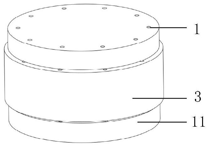
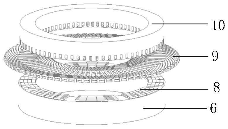
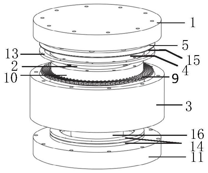
[0067] The implementation example of the present disclosure takes an 8-pole 72-slot disc permanent magnet synchronous motor as an example, figure 1 The overall structure of the energy storage flywheel based on magnetic suspension support proposed by the present invention includes an upper end cover 1, an upper radial magnetic bearing 2, a casing 3, a non-magnetic buckle 4, an upper magnetic disc 5, a rotor yoke 6, Rotating shaft 7, permanent magnet pole 8, armature winding 9, stator core 10, lower end cover 11, flywheel rotor 12, axial protective bearing 13, axial passive magnetic bearing 14,...

Embodiment 2

[0082] The purpose of this embodiment is to provide the installation steps of the disc permanent magnet synchronous motor and the energy storage flywheel: first install the integral flywheel rotor 12 in place, and then determine the stator disc 10 by measuring the axial position of the permanent magnet 8 on the upper end face of the flywheel rotor In order to ensure the axial clearance between the stator disk 10 and the rotor disk of the motor, in addition, the overall rotor needs to be positioned axially by installing a position sensor to ensure that the rotor disk of the motor will not be in the position of the stator disk 10. The suction effect is attached to the stator disk 10 .

Embodiment 3

[0084] The purpose of this embodiment is to provide a working method for a disc permanent magnet synchronous motor, including:

[0085] The air gap mentioned in the main magnetic circuit is the air gap a between the stator core 10 and the rotor disc, adding an additional Figure 11 Specifically describe the main magnetic circuit of the motor, and mark the air gap in the main magnetic circuit at the same time;

[0086] by Figure 11 As an example to illustrate the magnetic circuit of the motor, the permanent magnetic flux passes through the rotor disk permanent magnet 8-1→air gap a→stator tooth 10-11→stator yoke 10-2→adjacent stator tooth 10-12→air gap a→ Adjacent rotor disk permanent magnet 8-2→rotor yoke disk 6→finally return to the original rotor disk permanent magnet 8-1 to form a closed loop;

[0087]Two adjacent permanent magnets in the circumferential direction have opposite polarities. When the prime mover rotor 12 rotates, the permanent magnet poles 8 act as the roto...


PUM


Abstract

The invention provides a disc type permanent magnet synchronous motor, an energy storage flywheel based on magnetic suspension support and a method. The disc type permanent magnet synchronous motor comprises an upper stator disc and a lower rotor disc. The stator disc comprises a stator iron core, the stator iron core comprises stator teeth and a stator yoke, an armature winding is a short-moment distribution winding and is wound on the stator teeth, and winding coils are arranged in a double-layer mode in the axial direction. The rotor disc is composed of a rotor yoke disc and permanent magnets of which the N poles and S poles are arranged in a staggered manner in the circumferential direction, wherein the number of magnetic poles of the permanent magnets is uniform and the permanent magnets are embedded on the upper surface of the rotor yoke. The structure of the motor for the energy storage flywheel is optimized, the motor is an axial magnetic flux motor, the flywheel rotor serves as a magnetic conductive yoke disc of the lower rotor disc, the motor and the generator are integrated, mutual inverse operation of electric/power generation is achieved, the motor can work in an electric state and a power generation state, and the structure of a flywheel energy storage system is simplified.

Description

technical field [0001] The disclosure belongs to the technical field of motors, and in particular relates to a disc permanent magnet synchronous motor, an energy storage flywheel based on a magnetic suspension support and a method. Background technique [0002] The statements in this section merely provide background information related to the present disclosure and do not necessarily constitute prior art. [0003] With the rapid development of society, people consume more and more energy, and the electricity consumption of users is also increasing year by year. The environmental pollution caused by traditional thermal power is becoming more and more serious, forcing people to think about using new energy or renewable energy for research and development. application feasibility. In recent years, the state has given great support to low-carbon renewable energy, vigorously developed renewable energy technology, and green energy such as wind energy and solar energy has become ...

Claims


Application Information

Patent Timeline
Patent Type & Authority Applications(China)
IPC IPC(8): H02K21/24H02K1/16H02K1/18H02K1/27H02K3/28H02K7/02H02K7/09H02K9/19
CPCH02K21/24H02K1/16H02K1/182H02K1/2793H02K3/28H02K7/025H02K7/09H02K9/19H02K2201/12Y02E60/16
Inventor 徐衍亮孙铭鑫李根胜
Owner SHANDONG UNIV
Why Eureka
Try Eureka