
Production method of high-dielectric low-loss high-frequency microwave composite dielectric substrate

A high-frequency microwave and composite dielectric technology, which is applied in the field of ceramic materials for microwave electronic components and electronic components, can solve the problem of difficult preparation of high-dielectric, low-loss high-frequency microwave composite dielectric substrates, lack of continuous batch production capacity, loss major issues

Pending Publication Date: 2021-07-20
CHINA ZHENHUA GRP YUNKE ELECTRONICS
View PDF8 Cites 3 Cited by
  • Summary
  • Abstract
  • Description
  • Claims
  • Application Information

AI Technical Summary

Problems solved by technology

Solve the problems of existing microwave dielectric ceramic materials such as low dielectric constant, large loss, large temperature coefficient of resonant frequency, and lack of continuous batch production capacity
[0005] The technical concept adopted in the present invention is: by preparing high-dielectric microwave porcelain powder as filler, no longer using low-dielectric glass fiber cloth, and adopting pure ceramics to fill PTFE, it is difficult to prepare high-dielectric and low-loss materials in traditional production processes. High-frequency microwave composite dielectric substrate

Method used


Image

  • Production method of high-dielectric low-loss high-frequency microwave composite dielectric substrate
  • Production method of high-dielectric low-loss high-frequency microwave composite dielectric substrate
  • Production method of high-dielectric low-loss high-frequency microwave composite dielectric substrate

Examples


specific Embodiment approach

[0030] The specific embodiment of content of the present invention is as follows:

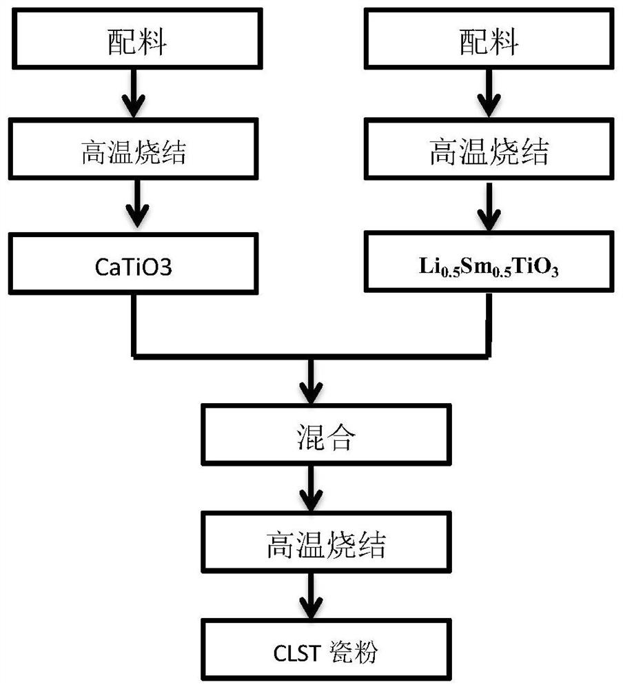
[0031] (1) by 0.6CaTiO 3 +0.4Li 0.5 SM 0.5 TiO 3 molar ratio for batching;

[0032] (2) planetary ball mill;

[0033] (3) High-temperature sintering, the sintering temperature is 1150° C., and the time is 2 hours, to prepare high-dielectric microwave porcelain powder for later use;

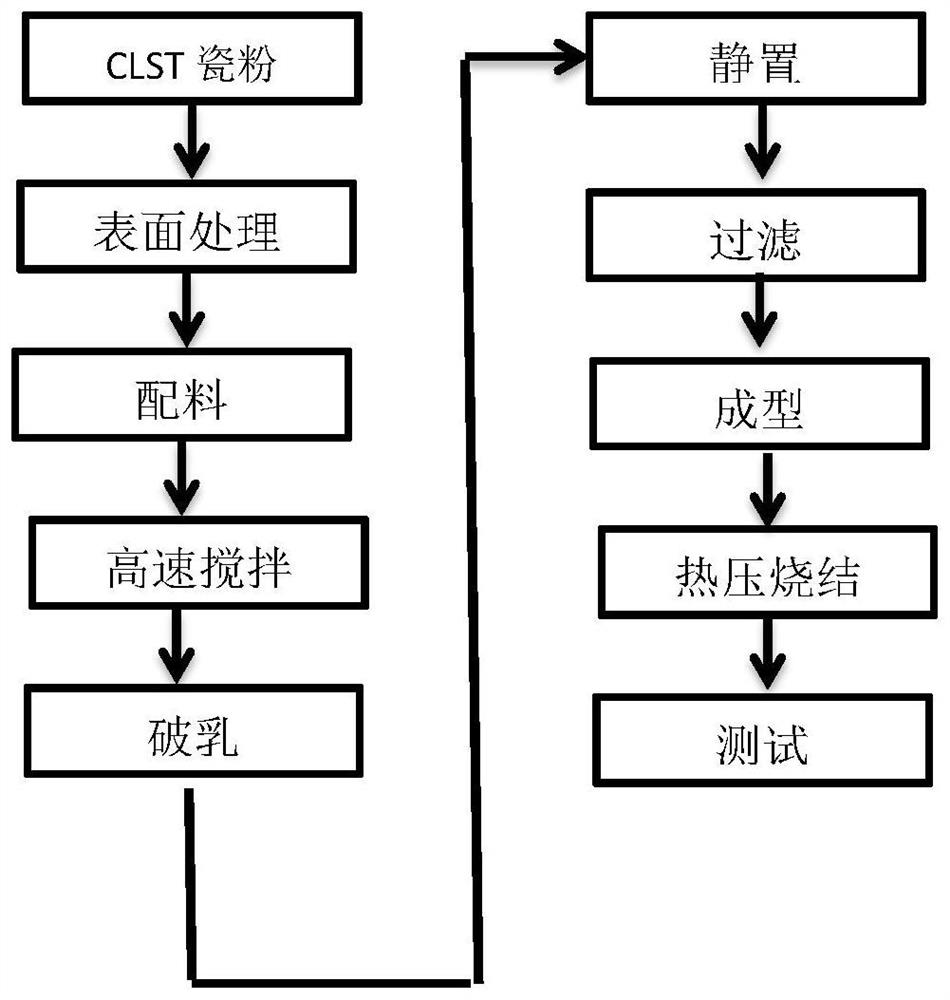
[0034] (4) Use silane coupling agent KH550 to carry out surface treatment to the porcelain powder, and the dosage of KH550 is 1.5wt% of the quality of the porcelain powder;

[0035] (5) According to (1-x) CLST porcelain powder + x polytetrafluoroethylene emulsion (wherein x is the mass percentage, 0.7≥x≥0.6) for batching, fully stir;

[0036] (6) Add alcohol as a demulsifier, stir at high speed for 30 minutes, and rotate at a speed of 400r / min to 800r / min;

[0037] (7) The mixed solution was allowed to stand for 6 hours, and filtered to obtain the compound dough;

[0038] (8) Composite dough calendering;

...


PUM


Abstract

The invention discloses a preparation method of a high-dielectric low-loss high-frequency microwave composite dielectric substrate, and belongs to the field of microwave electronic component ceramic materials, wherein the preparation method comprises the following steps: preparing CaTiO3 and Li0.5Sm0.5TiO3 according to a molar ratio to form CLST ceramic powder; ball-milling the ceramic powder; sintering at high temperature; carrying out surface treatment on the ceramic powder by using a silane coupling agent; proportioning the ceramic powder subjected to surface treatment and polytetrafluoroethylene emulsion; adding a demulsifier for demulsification; standing and filtering to form composite dough; carrying out calendering molding or compression molding; and carrying out hot pressed sintering on a molded green body coated with copper foils on two surfaces to form the high-dielectric low-loss high-frequency microwave composite dielectric substrate. The problems that an existing microwave dielectric ceramic material is low in dielectric constant, large in loss, large in temperature coefficient of resonance frequency and free of continuous batch production capacity are solved. The substrate is widely applied to the modern microwave electronic communication fields of spaceflight electronic equipment circuit boards, satellite communication, Beidou systems and the like.

Description

technical field [0001] The invention belongs to the field of electronic components, specifically, to the field of microwave electronic components, and more specifically, to the field of ceramic materials for microwave electronic components. Background technique [0002] Microwave dielectric ceramics (MWDC) refer to ceramic materials that are used as dielectric materials in microwave frequency (300MHz-300GHz) circuits and perform one or more functions. In microwave electronic components, microwave dielectric ceramics are the key materials for making microwave resonators and filters. frequency, with a near-zero resonant frequency temperature coefficient to ensure the stability of the device. At present, although the widely used microwave dielectric ceramic materials meet the requirements of some electronic components in terms of performance, with the deepening of research on satellite applications, deep space exploration and manned spaceflight, high-capacity, high-frequency a...

Claims


Application Information

Patent Timeline
IPC IPC(8): C04B35/465C04B35/622C04B35/645
CPCC04B35/465C04B35/622C04B35/645C04B2235/3203C04B2235/3224C04B2235/6567
Inventor 杨俊班秀峰庞锦标韩玉成张秀姚朝宗应建
Owner CHINA ZHENHUA GRP YUNKE ELECTRONICS
Learn More