Efficient enzymolysis system of microbial preparation
A microbial preparation and high-efficiency technology, applied in the field of enzymatic hydrolysis, can solve the problems of uneven stirring, uneven heating, and difficult discharge of materials in vertical enzymatic hydrolysis tanks, so as to facilitate feeding and internal maintenance, and uniform and consistent heating temperature , to reduce the residual effect
- Summary
- Abstract
- Description
- Claims
- Application Information
AI Technical Summary
Problems solved by technology
Method used
Image
Examples
Embodiment 1
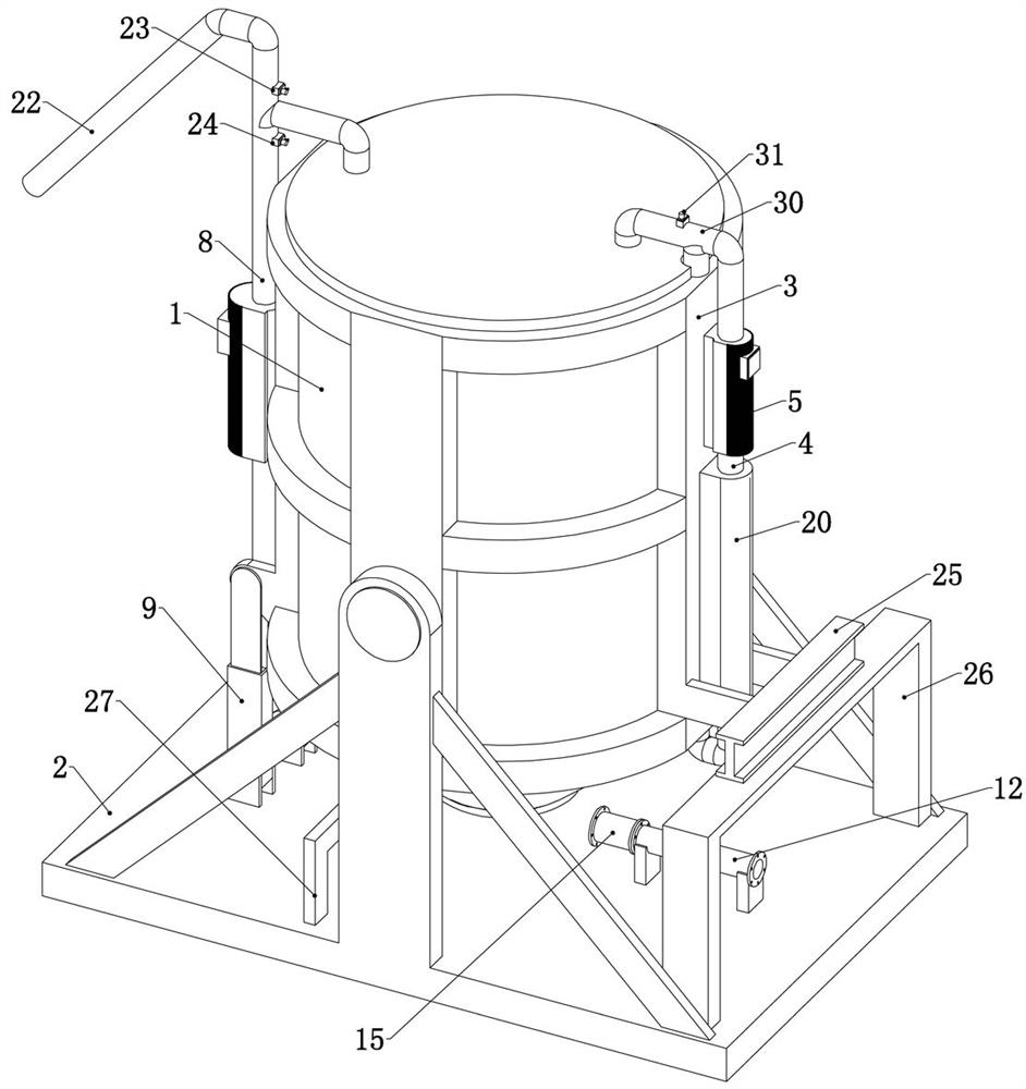
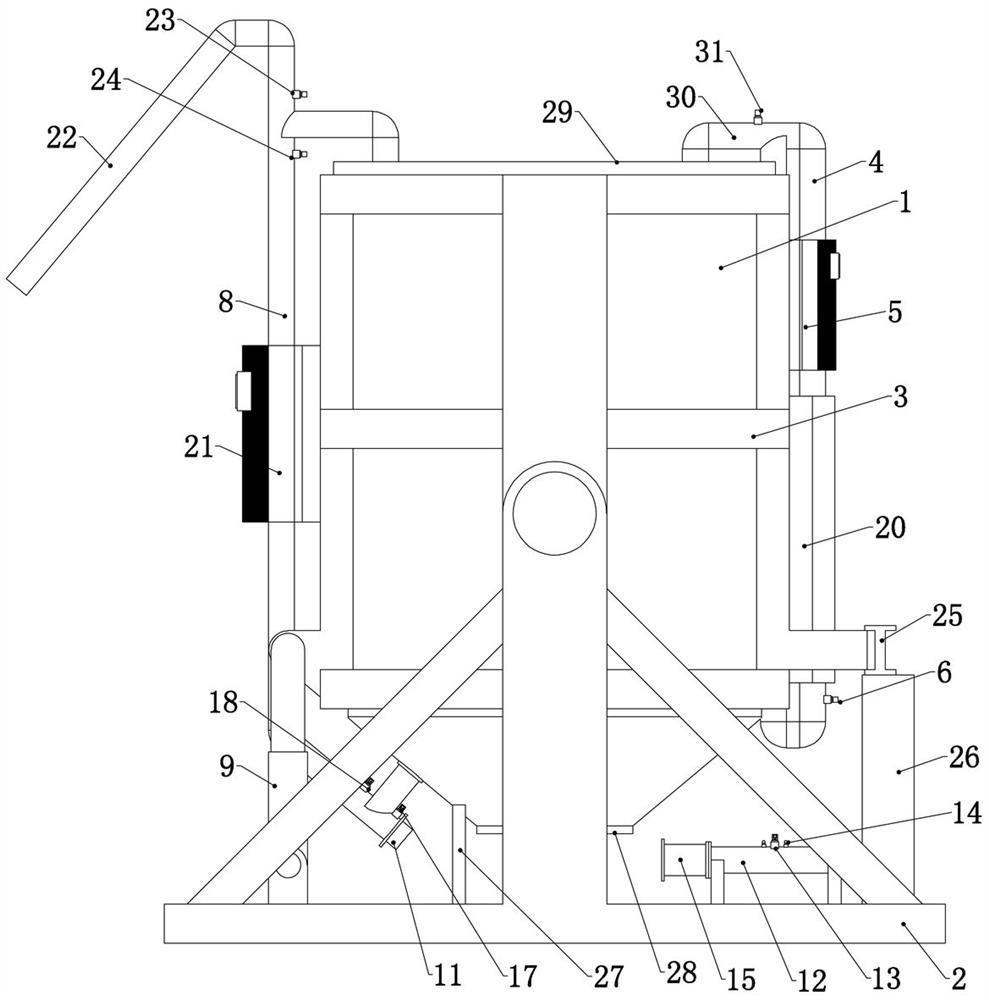
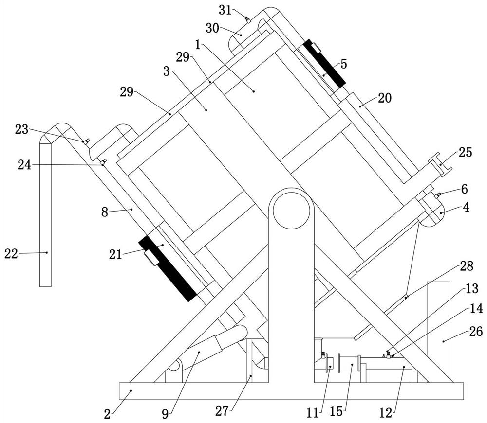
[0057]Embodiment 1, the present invention is a high-efficiency enzymatic hydrolysis system for microbial preparations, including a tank 1 and a base 2, the base 2 is placed on the ground, the tank 1 is rotatably connected to the base 2, and it is characterized in that it also includes Insulation air pipe 3, there are multiple heat insulation air pipes 3 and all surround the side wall of the tank body 1, the multiple heat insulation air pipes 3 are connected to each other, and the heat insulation air pipe 3 is filled with heat preservation gas, so as to ensure the temperature of the tank body 1, All the heat preservation air pipes 3 are connected to each other and form a complete heat preservation and heating system;
[0058] Circulation pipe 4, the two ends of the circulation pipe 4 communicate with the uppermost heat insulating air pipe 3 and the lowermost heat insulating air pipe 3 respectively, and the air pump 5 fixedly connected to the tank body 1 is arranged on the descri...
Embodiment 2
[0063] Embodiment 2. On the basis of Embodiment 1, the end of the return pipe 8 close to the tapered portion 7 is fixedly connected with a discharge pipe 11. When the hydraulic cylinder 9 is in the shrinking position, the axis of the discharge pipe 11 is horizontal;
[0064] Also includes a discharge pipe 12, the discharge pipe 12 is detachably connected to the base 2, the discharge pipe 12 is provided with a discharge valve 13, and the discharge valve 13 can connect the discharge pipe 12 partitions, the two ends of the discharge valve 13 are provided with a pressure relief valve 14 on the discharge pipe 12, when the pressure relief valve 14 is opened, the discharge pipe 12 communicates with the external air, and the discharge pipe 12 One end of the sliding sleeve is provided with a sliding tube 15, and the other end of the sliding tube 15 can communicate with the discharge tube 11. When the sliding tube 15 stretches out, the other end of the sliding tube 15 is sleeved outside ...
Embodiment 3
[0067] Embodiment three, on the basis of embodiment one, refer to figure 1 , figure 2 , image 3 , the end of the return pipe 8 close to the upper end of the tank body 1 is fixedly connected with a feed pipe 22, and external materials can enter the tank body 1 through the feed pipe 22, refer to image 3 , when the hydraulic cylinder 9 is located at the shrinking position, the tank body 1 is tilted, and the feed pipe 22 is vertically downward, and the feed pipe 22 is provided with a first feed valve 23, and the first feed There is a second feed valve 24 arranged on the return pipe 8 on one side of the valve 23. When the first feed pipe 22 is closed, external materials cannot enter the tank body 1 through the feed pipe 22, and the second feed valve When 24 was closed, the circulation pipe 4 was closed.
PUM
 Abstract
Description
Claims
Application Information
 - R&D
- Intellectual Property
- Life Sciences
- Materials
- Tech Scout
- Unparalleled Data Quality
- Higher Quality Content
- 60% Fewer Hallucinations
Browse by: Latest US Patents, China's latest patents, Technical Efficacy Thesaurus, Application Domain, Technology Topic, Popular Technical Reports.
© 2025 PatSnap. All rights reserved.Legal|Privacy policy|Modern Slavery Act Transparency Statement|Sitemap|About US| Contact US: help@patsnap.com


