Microwave drying oven for coal quality detection
A drying box and quality technology, which is used in drying, dryer, fuel testing and other directions, can solve the problems that heat cannot be recycled and water vapor cannot be collected in the drying box.
- Summary
- Abstract
- Description
- Claims
- Application Information
AI Technical Summary
Problems solved by technology
Method used
Image
Examples
Embodiment 1
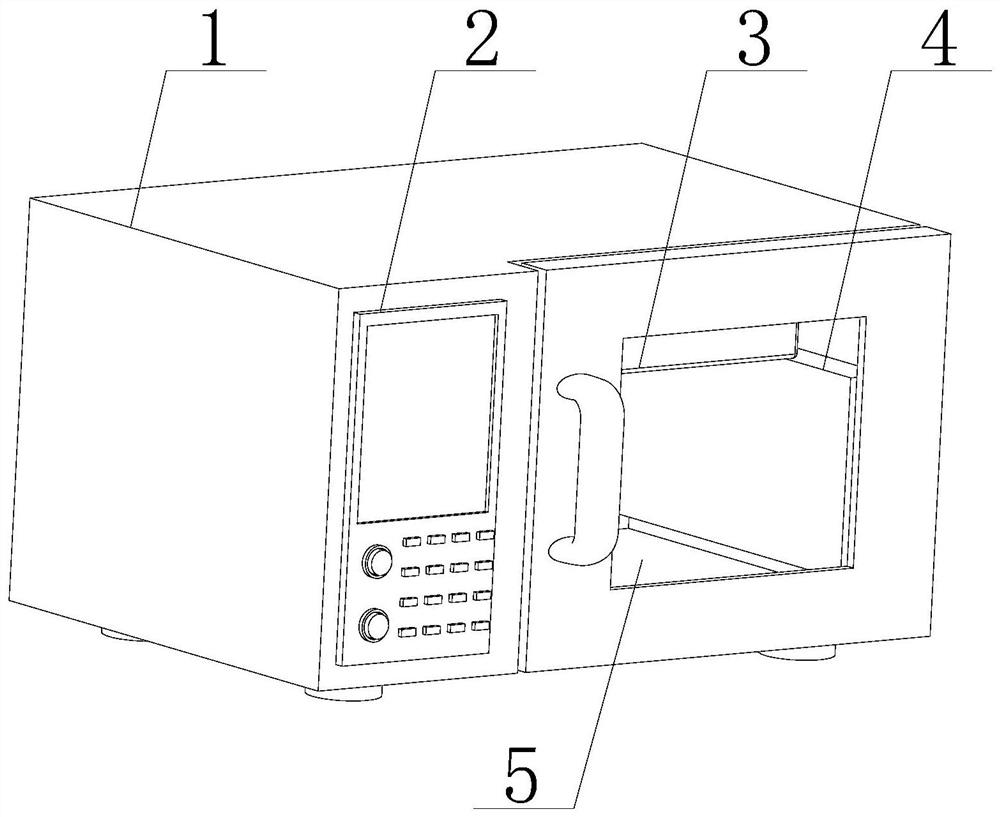
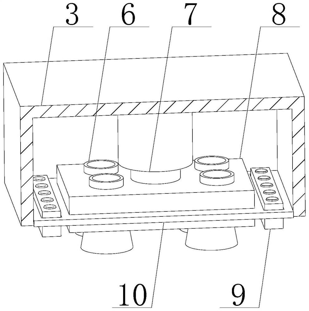
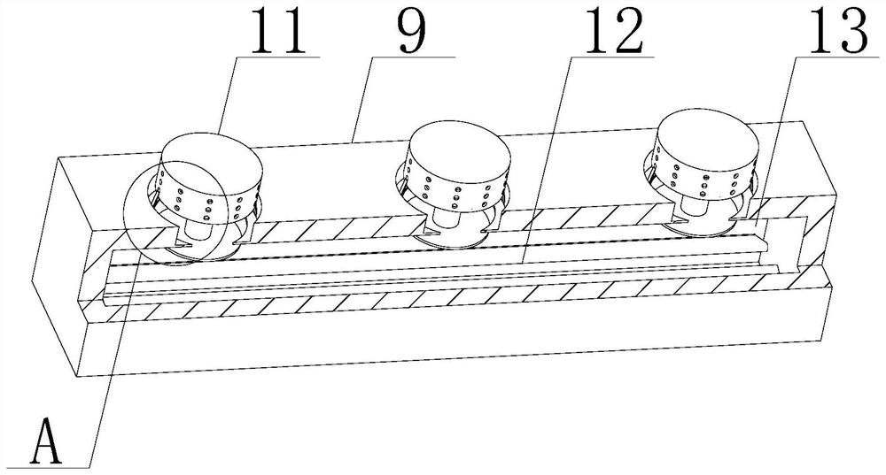
[0039] Such as Figure 1-7As shown, the present invention provides a microwave drying box for coal quality detection, comprising a drying box body 1, a control panel 2 and a drying cavity 5, the front of the drying box body 1 is provided with a drying cavity 5, and the drying box The front of the main body 1 and the left side of the drying chamber 5 are embedded with a control panel 2, the top of the inner wall of the drying chamber 5 is fixedly installed with a circulation box 3, and the bottom of the circulation box 3 is fixedly connected with an electric adjustment rod 7. The bottom of the rod 7 is fixedly connected with a thermal insulation block 8, and the both sides of the inner wall of the drying chamber 5 are fixedly equipped with a water vapor collection frame 4, and the inner wall of the water vapor collection frame 4 is fixedly installed with a cooling water collection box 23, and the inner wall of the cooling water collection box 23 is located at The bottom of the ...
Embodiment 2
[0041] Such as Figure 1-7 As shown, on the basis of Example 1, the present invention provides a technical solution: preferably, the bottom of the heat insulating block 8 is provided with a heat pipe 6, and the top of the heat pipe 6 runs through the top of the heat insulating block 8, and the heat pipe 6 The heating tube 17 is slidably connected to the bottom of the heating tube, and the hot air entering the circulation box 3 can enter the heating tube 17 through the heat pipe 6. The outer wall of the heat pipe 6 is hinged with a movable clamping plate 18, and the side of the movable clamping plate 18 is fixed. An expansion block 19 is connected, and the side of the expansion block 19 away from the movable clamping plate 18 is fixedly connected with the outer wall of the heat pipe 6. After the expansion block 19 is heated, it can push the movable clamping plate 18 to move, thereby adjusting the height of the heating cylinder 17 , it is convenient to make the heat in the heati...
Embodiment 3
[0043] Such as Figure 1-7 As shown, on the basis of Embodiment 1, the present invention provides a technical solution: preferably, the top of the collection box 22 is provided with a water collection chamber 26, and the inner wall of the water collection chamber 26 is hinged with a barrier plate 21, and the barrier plate 21 can The water flowing down is blocked to prevent the water in the water collection chamber 26 from evaporating again. The bottom of the barrier plate 21 is hinged with a spoiler 25, and the top of the collection box 22 is set as an inclined plane. The water slides down, the bottom of the spoiler 25 is slidingly connected with the top of the collection box 22, the side of the spoiler 25 is fixedly connected with an elastic piece 24, and the other end of the elastic piece 24 is fixedly connected with the bottom of the barrier plate 21, so that the water flow can push The baffle plate 25 deflects its angle, and when the baffle plate 25 rotates, the elastic sh...
PUM
 Abstract
Description
Claims
Application Information
 - R&D
- Intellectual Property
- Life Sciences
- Materials
- Tech Scout
- Unparalleled Data Quality
- Higher Quality Content
- 60% Fewer Hallucinations
Browse by: Latest US Patents, China's latest patents, Technical Efficacy Thesaurus, Application Domain, Technology Topic, Popular Technical Reports.
© 2025 PatSnap. All rights reserved.Legal|Privacy policy|Modern Slavery Act Transparency Statement|Sitemap|About US| Contact US: help@patsnap.com


