Power generation system
A power generation system, fuel cell technology, applied in the direction of circuits, power system fuel cells, electrical components, etc., can solve problems such as power generation efficiency reduction
- Summary
- Abstract
- Description
- Claims
- Application Information
AI Technical Summary
Problems solved by technology
Method used
Image


Examples
Embodiment approach
[0044] Hereinafter, an embodiment will be described for a power generation system including: a fuel cell having a negative electrode and a positive electrode; a pipe (anode gas supply path) for supplying hydrogen-containing gas to the negative electrode of the fuel cell; And the separator that houses the separation membrane (which separates hydrogen from other gases). Other known techniques may be combined in this embodiment.
[0045] (1-1) Overall structure
[0046] [first way]
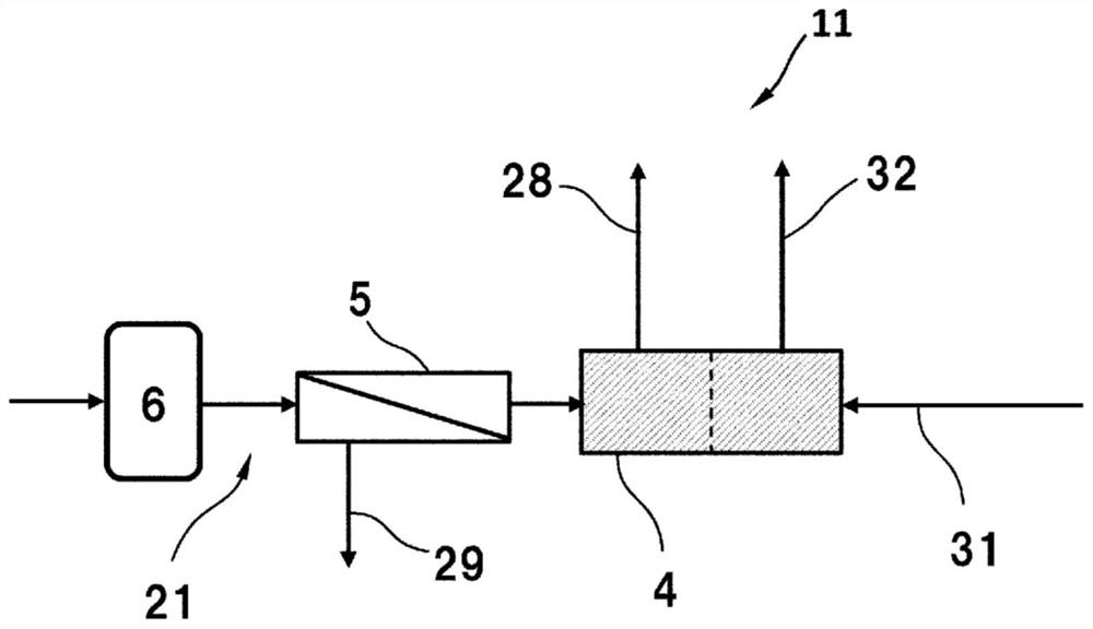
[0047] figure 1 It is a schematic diagram showing one embodiment of the power generation system of the present invention.
[0048] figure 1 The power generation system 11 shown includes: anode gas supply piping 21, anode exhaust piping 28, non-permeable gas piping 29, anode gas supply piping 31, anode exhaust piping 32, fuel cells 4, separators 5, and hydrogen storage tanks. 6.
[0049] The anode gas supply pipe 21 is an example of an anode gas supply path, is connected to the anode-side inlet ...
Embodiment
[0229] Hereinafter, although an Example demonstrates this invention in more detail, this invention is not limited to these Examples at all. Hereinafter, unless otherwise specified, the temperature is 25°C. In addition, mass % is shown as wt%.
[0230] I. Separation membrane with polyamide separation function layer
manufacture example
[0231] [Production examples (1) to (8) of separation membranes]
[0232] (Formation of porous support layer)
[0233] In non-woven fabric (made of polyester, air flow 2.0cc / cm) as the base material 2 / sec) A 16.0 wt % DMF solution of polysulfone (PSf) was cast at 25° C. to a thickness of 200 μm, immediately immersed in pure water and left for 5 minutes to form a porous support layer. Thus, a support membrane having a base material and a porous support layer was produced.
[0234] (Formation of separation functional layer)
[0235] The support film obtained by the above operation was immersed in a 6.0 wt % m-PDA aqueous solution for 2 minutes. Next, the supporting film was slowly lifted up in the vertical direction and nitrogen was blown from an air nozzle, thereby removing excess amine aqueous solution from the surface of the porous supporting layer. Next, a TMC (trimesoyl chloride) solution having a composition described in Table 3 was applied so as to wet the entire surf...
PUM
| Property | Measurement | Unit |
|---|---|---|
| pore size | aaaaa | aaaaa |
| thickness | aaaaa | aaaaa |
| diameter | aaaaa | aaaaa |
Abstract
Description
Claims
Application Information