A cranial repositioner with a splint
A technology of reducer and skull, which is applied in the field of skull reducer, can solve the problems of high clinical experience requirements, poor compatibility of skull tissue, deviation between bone flap and skull, etc., and the process of bone flap reduction and connection and fixation is simple and convenient. Improve adjustment and stable support, good effect of adjustable performance
- Summary
- Abstract
- Description
- Claims
- Application Information
AI Technical Summary
Problems solved by technology
Method used
Image
Examples
Embodiment 1
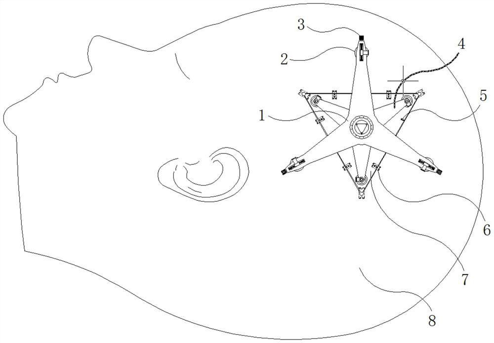
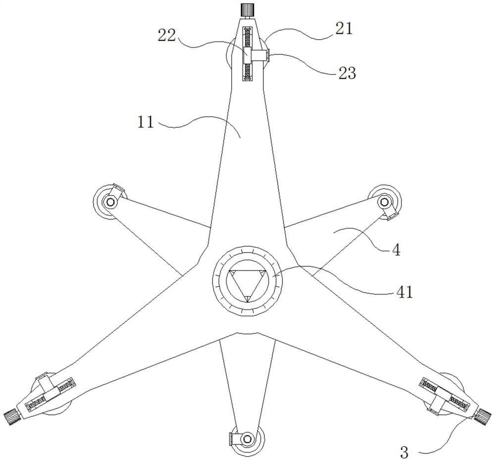
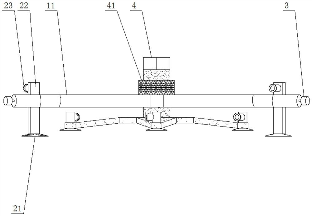
[0037] Refer to attached figure 1 , Figure 4 , Figure 5 with Image 6 As shown, according to the size and shape of the patient's defect, the doctor made a bionic skull bone flap 7 that fit the patient's defect or directly used an autologous bone flap 7. Grooves were ground on the bone flap 7 along the vertical direction of its interface and Put the sinking screw 5 into the bone flap 7 in advance and tighten it, the transfer device 4 will hold the bone flap 7, and the corrugated frame 1 will be sucked tightly above the defect 81 of the skull 8 through the sucking device 2, and the corrugated frame 1 The transfer device 4 that holds the bone flap 7 can be driven to move in a plane through the adjustment device 3, and the transfer device 4 that holds the bone flap 7 can also rotate and move up and down on the corrugated frame 1 and be compressed by the compression cover 41, The bone flap 7 is accurately placed in the defect 81 of the skull 8 to align and stabilize its positi...
Embodiment 2
[0040] On the basis of embodiment one, refer again Figure 7 As shown, the sinking screw 5 is made of titanium alloy material, and the sinking screw 5 may include: a clamping sleeve 51, a rotating lever 52, a convex and sliding dial 53, a spiral connecting column 54, a horizontal bolt locking rod 55, and a bolt expanding The tip 56 and the clamp sleeve 51 are pressed in the groove formed by the bone flap 7. The lower half of the clamp sleeve 51 is a cylinder and the upper half is a square body, so as to ensure that the clamp sleeve 51 is clamped in the bone flap 7 and will not rotate. ; The inside of the clamping sleeve 51 is a threaded hole, the rotary rod 52 is concentric with the axis of the inner hole of the clamping sleeve 51, the rotary rod 52 is rotated and blocked and connected to the clamping sleeve 51, and the rotary rod 52 is a circular rod shape, the rod of the rotary rod 52 is milled with a long bar hole, the outer side of the rotary rod 52 is a cap shape, and the...
PUM
 Abstract
Description
Claims
Application Information
 - R&D
- Intellectual Property
- Life Sciences
- Materials
- Tech Scout
- Unparalleled Data Quality
- Higher Quality Content
- 60% Fewer Hallucinations
Browse by: Latest US Patents, China's latest patents, Technical Efficacy Thesaurus, Application Domain, Technology Topic, Popular Technical Reports.
© 2025 PatSnap. All rights reserved.Legal|Privacy policy|Modern Slavery Act Transparency Statement|Sitemap|About US| Contact US: help@patsnap.com


