Shifting centering type micro-lens array machining device and method

A microlens array and processing device technology, applied in the direction of fine working devices, auxiliary devices, stone processing equipment, etc., can solve problems affecting the application and promotion of microlens arrays, changes in cutting speed of tools, and unstable processing quality, etc., to achieve The effects of stable motion control, reduced assembly error, and high positioning accuracy

Active Publication Date: 2021-08-06
霖鼎光学(上海)有限公司
View PDF5 Cites 5 Cited by
  • Summary
  • Abstract
  • Description
  • Claims
  • Application Information

AI Technical Summary

Problems solved by technology

However, due to the change of the radius of rotation at the same speed, the cutting speed of the tool will also change continuously, and the tracking frequency of the fast tool servo will be required to be higher and higher. Insufficient bandwidth, etc.
In addition, the cost of equipment required by this method is relatively high, and the economy is poor.
[0006] It can be seen that the existing various microlens array processing devices and methods all have problems such as low processing efficiency, high equipment cost, and unstable processing quality, which seriously affect the application and application of microlens arrays, an excellent optical performance element. to promote

Method used


Image

  • Shifting centering type micro-lens array machining device and method
  • Shifting centering type micro-lens array machining device and method
  • Shifting centering type micro-lens array machining device and method

Examples


Embodiment Construction

[0033] Below in conjunction with specific embodiment, further illustrate the present invention. It should be understood that these examples are only used to illustrate the present invention and are not intended to limit the scope of the present invention. In addition, it should be understood that after reading the teachings of the present invention, those skilled in the art can make various changes or modifications to the present invention, and these equivalent forms also fall within the scope defined by the appended claims of the present application.

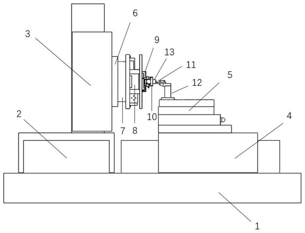
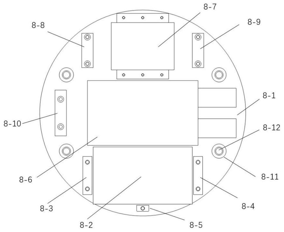
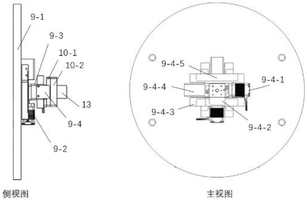
[0034] The present invention proposes an axis-shifting centered microlens array processing device, such as Figure 1-3 As shown, it mainly consists of base 1, machine tool X axis 2, machine tool Y axis 3, machine tool Z axis 4, machine tool B axis 5, machine tool C axis 6, diamond tool 11, diamond tool holder 12, vacuum chuck 7, control module 8. It consists of a two-dimensional positioning module 9 and a workpiece fixture 10....


PUM


Abstract

The invention relates to a shifting centering type micro-lens array machining device and method. The device comprises a base, a machine tool X shaft and a machine tool Y shaft are installed on the base, the moving directions of the machine tool X shaft and the machine tool Y shaft are perpendicular to each other, a machine tool Z shaft is arranged on a sliding table of the machine tool X shaft, the moving direction of the machine tool Z shaft is perpendicular to the machine tool X shaft and the machine tool Y shaft, a machine tool B shaft is arranged on the machine tool Z shaft, and a machine tool C shaft is arranged on the machine tool Y shaft. The machining device is characterized in that a machining tool is fixed to the surface of the machine tool B shaft; a vacuum suction cup is fixed to the surface of the machine tool C shaft, a control module is fixed to the surface of the vacuum suction cup, a two-dimensional positioning module is installed on the control module, and a workpiece clamp is installed on the two-dimensional positioning module; and the two-dimensional positioning module is used for adjusting the relative position of the workpiece to be machined on the workpiece clamp and the machine tool C shaft. According to the shifting centering type micro-lens array machining device and method, the machining efficiency of the micro-lens array can be improved, and the machining quality of each micro-lens unit is unified.

Description

technical field [0001] The invention relates to the technical field of ultra-precision machining, in particular to an axis-shifting centering microlens array processing device and method. Background technique [0002] Microlens array refers to a microstructured surface with specific optical properties obtained after a regular array of microlenses is distributed. It is widely used in optoelectronic fields such as lighting, beam shaping, and optical imaging. At present, the processing methods of microstructured surfaces mainly include photolithography technology, high-energy beam manufacturing technology, special energy field processing technology and ultra-precision machining technology. Photolithography technology is to use exposure technology to form the required geometric structure pattern on the surface of photoresist, and then engrave the pattern on the substrate by etching method. This method has high manufacturing resolution, but it is usually only suitable for binary ...

Claims


Application Information

Patent Timeline
Patent Type & Authority Applications(China)
IPC IPC(8): B23B5/00B23B25/06B28D1/16B28D5/00
CPCB23B5/00B23B25/06B28D1/16B28D5/00
Inventor 张鑫泉王震东任明俊张哲朱利民
Owner 霖鼎光学(上海)有限公司
Why Eureka
Try Eureka