
Automatic treatment system and method for H2S waste gas

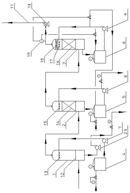
A waste gas and automatic valve technology, which is applied in chemical instruments and methods, separation methods, dispersed particle separation, etc., can solve the problems of high treatment cost, low degree of automation, and high labor intensity, so as to reduce the consumption of liquid caustic soda and reduce treatment cost, to achieve the effect of automatic unmanned operation

Inactive Publication Date: 2021-08-10
JINCHUAN GROUP LIMITED
View PDF5 Cites 0 Cited by
  • Summary
  • Abstract
  • Description
  • Claims
  • Application Information

AI Technical Summary

Problems solved by technology

[0003] In view of the above technical problems, the present invention provides a vehicle guide device for a T-shaped fork in the mine. 2 S exhaust gas is absorbed, resulting in H 2 The cost of S up-to-standard treatment is high. At the same time, the replacement process after the absorption of liquid caustic soda reaches the saturation point is a manual operation with a low degree of automation and high labor intensity. The replacement process will easily lead to H 2 The problem of excessive S

Method used


Image

  • Automatic treatment system and method for H2S waste gas

Examples


Embodiment 1

[0038] the above H 2 The automatic treatment device and method of S exhaust gas are applied to a certain system, working conditions: exhaust gas volume 3000Nm 3 / h, H 2 The concentration of S is 200-500ppm, and the specific steps are: add 10% sodium sulfide solution through the automatic valve in the sodium sulfide circulation tank 5, close the automatic valve and start the sodium sulfide circulation pump 8 after the liquid level of the sodium sulfide circulation tank reaches 2m; 6. Add 10% lye through the automatic valve, and close the automatic valve to start the liquid-alkali circulation pump at a liquid level of 2m in the liquid-alkali circulation tank; 3 The flow rate of / h enters the acid water circulation tank 4, and the liquid level reaches 1.5m to start the acid water circulation pump 7, and adjust the acid water delivery pump 20 outlet flow to 30m 3 / h, stabilize the liquid level of the acid water circulation tank 4 at about 1.5m; open the induced draft fan 10 to r...

Embodiment 2

[0040] With embodiment 1, above-mentioned H 2 The automatic treatment device and method of S waste gas are applied to another H 2 System with high S concentration, working conditions: exhaust gas volume 7000 Nm 3 / h, H 2 The concentration of S is 600-900ppm, and the specific steps are: add 15% sodium sulfide solution through the automatic valve in the sodium sulfide circulation tank 5, close the automatic valve and start the sodium sulfide circulation pump 8 after the liquid level of the sodium sulfide circulation tank reaches 2m; 6. Add 15% lye through the automatic valve, and close the automatic valve to start the liquid-alkali circulation pump at a liquid level of 2m in the liquid-alkali circulation tank; 3 The flow rate of / h enters the acid water circulation tank 4, and the liquid level reaches 1.5m to start the acid water circulation pump 7, and adjust the acid water delivery pump 20 outlet flow to 50m 3 / h, stabilize the liquid level of the acid water circulation tan...


PUM


Abstract

The invention discloses an automatic treatment system for H2S waste gas. The system comprises an acid water absorption tower, the gas inlet end at the bottom of the acid water absorption tower is connected with H2S gas conveying equipment through a pipeline, and an acid water spray head is arranged in the acid water absorption tower. The invention also discloses an automatic treatment method for H2S waste gas. The method comprises the following steps: A, H2S gas generated in the vulcanization reaction tank enters from the lower part of the acid water absorption tower; b, the acid wastewater is controlled by an automatic valve and a flow meter on a liquid inlet pipe on the top of the acid water circulating tank; and C, an automatic valve and a liquid level meter on a liquid inlet pipe at the top of the sodium sulfide circulating tank are interlocked. The system and the method can solve the problems that the H2S standard treatment cost is high due to the fact that liquid caustic soda is commonly used for absorbing H2S waste gas in the industry at present, and meanwhile, the replacement process after liquid caustic soda absorption reaches a saturation point is manually operated, the automation degree is low, the labor intensity of personnel is high, and H2S is likely to exceed the standard in the replacement process.

Description

technical field [0001] The invention relates to the technical fields of chemical environmental protection and automatic control, in particular to a H 2 An automatic treatment system and method for S waste gas. Background technique [0002] A large amount of heavy metal acidic wastewater will be produced in the pyrometallurgy production process. The acidic wastewater treatment mostly adopts the sulfuration method to precipitate heavy metal ions, and H 2 S gas escapes. At present, liquid caustic soda (NaOH solution) is commonly used in the industry for H 2 S waste gas is absorbed, because the market price of liquid caustic soda is higher, resulting in H 2 The cost of S standard treatment is high; the absorption of liquid caustic soda reaches the saturation point, and fresh liquid caustic must be added after replacement. The replacement process is manual operation, with low degree of automation and high labor intensity, and the replacement process is easy to cause H 2 S exc...

Claims


Application Information

Patent Timeline
Patent Type & Authority Applications(China)
IPC IPC(8): B01D53/14B01D53/30B01D53/34B01D53/52B01D53/78B01D53/96B01D53/18
CPCB01D53/1468B01D53/1406B01D53/1493B01D53/78B01D53/52B01D53/96B01D53/30B01D53/346B01D53/18B01D2252/10B01D2252/103B01D2251/304B01D2251/604
Inventor 毛艳丽李山东王科红陈虎宋小虎马莹朱昊天程华花吴智娟张雪峰宋超
Owner JINCHUAN GROUP LIMITED
Learn More