
Balloon catheter

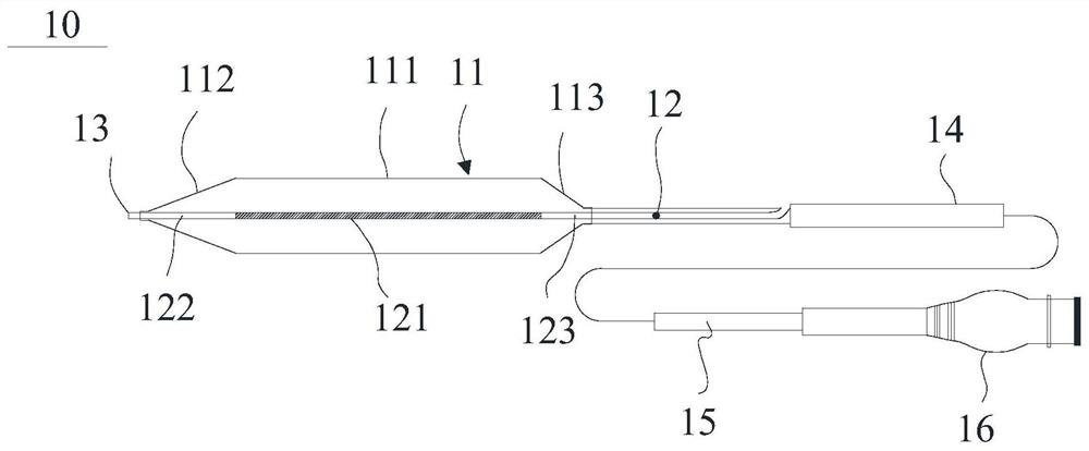
A balloon catheter and balloon technology, which is applied to balloon catheters and other directions, can solve the problems that the end of the balloon catheter cannot guide the guide wire to fit, affecting the trackability, pushability, and poor pushing performance of the balloon catheter.

Pending Publication Date: 2021-08-13
SHANGHAI BIOCHAM MEDICAL TECH CO LTD
View PDF0 Cites 0 Cited by
  • Summary
  • Abstract
  • Description
  • Claims
  • Application Information

AI Technical Summary

Problems solved by technology

On the premise of meeting the development requirements, the metal ring needs to have a certain wall thickness and length. Because the metal ring is difficult or incompressible, it may become the part with the largest outer diameter on the balloon body. Disadvantages such as non-bendable / poor flexibility in the middle lead to discounts on the inner lumen, poor push performance and even failure to reach the lesion, which affects the surgical results
[0007]Similar to but different from the lumen tube, the end (tip) of the balloon catheter is the most distal end of the whole balloon catheter system, which is too soft and easy to If it is damaged, it will affect the tracking and pushing performance of the balloon catheter. If it is too hard, it will make it difficult for the balloon catheter to pass through tortuous lesions, so it needs to have a certain degree of flexibility.
When the balloon catheter is pushed into the blood vessel by the doctor, if the end has a double-layer or multi-layer structure, it may be deformed or delaminated under the external pressure of the blood vessel wall, resulting in the end of the balloon catheter being unable to stick to the guide wire If it fits well, the tracking and pushing performance of the balloon catheter will be poor or even fail to reach the lesion, which will affect the operation result

Method used


Image

  • Balloon catheter
  • Balloon catheter
  • Balloon catheter

Examples


Embodiment Construction

[0055] Example embodiments will now be described more fully with reference to the accompanying drawings. However, example embodiments may be embodied in many forms, and the invention should not be construed as limited to the embodiments set forth herein; rather, these embodiments are provided so that this disclosure will be thorough and complete, and will incorporate the concepts of example embodiments Fully conveyed to those skilled in the art. The same reference numerals denote the same or similar structures in the drawings, and thus their repeated descriptions will be omitted. "Or" and "or" in the specification may mean "and" or "or".

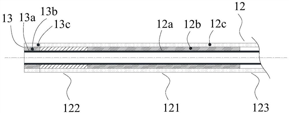
[0056] The present invention provides a balloon catheter, comprising a balloon body, a lumen tube and an end tube, the inner lumen tube runs through the balloon body, the end tube is connected to the distal end of the balloon body and / or The distal end of the lumen tube is connected, the lumen tube and / or the end tube includes a support la...


PUM

PropertyMeasurementUnit
Widthaaaaaaaaaa
Depthaaaaaaaaaa

Abstract

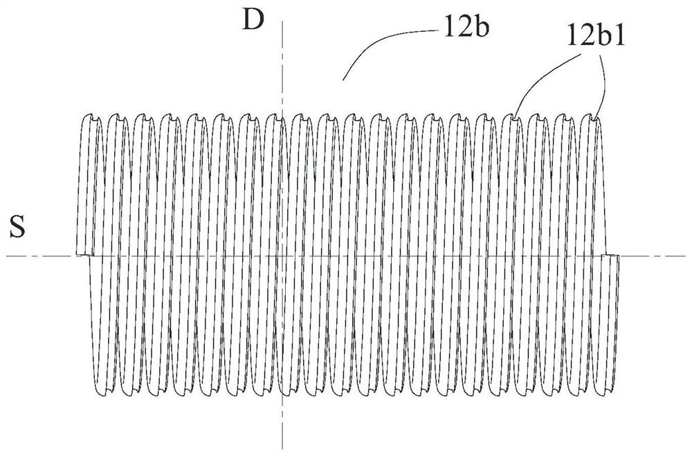
The invention provides a balloon catheter. The balloon catheter comprises a balloon body, an inner cavity tube and a tail end tube, wherein the inner cavity tube penetrates through the balloon body, the tail end tube is connected with the far end of the balloon body and / or the far end of the inner cavity tube, the inner cavity tube and / or the tail end tube comprise / comprises a support layer, and the support layer is made of a wire; and the inner cavity tube and / or the tail end tube further comprise / comprises an inner layer located on the inner side of the support layer and / or an outer layer located on the outer side of the support layer, and at least one groove is formed in at least one side surface of the support layer. The support layer is added to the inner cavity tube and / or the tail end tube, so that the inner cavity tube and / or the tail end tube cannot deform to tightly hold a guide wire; and the grooves are formed in the surface of the support layer, so that the combination contact area between the support layer and other layers of the inner cavity tube is increased, the combination strength between two or more layers is improved, and the layering phenomenon in the use process is avoided.

Description

technical field [0001] The invention relates to the technical field of medical instruments, in particular to a balloon catheter. Background technique [0002] Ischemic stroke is mainly due to vascular stenosis, occlusion / changes in hemodynamics or blood components, resulting in insufficient oxygen-carrying and nutrient substances in the blood or reduced clearance of metabolites, and the death of neurons / glial cells and blood vessels in the brain, accounting for about 80% of cerebrovascular diseases, and cerebrovascular stenosis is an important cause of disease and risk factors for ischemic cerebrovascular diseases. The main treatments currently used to treat cerebrovascular stenosis are: [0003] (i) Drug therapy, combined with anti-platelet aggregation / lipid-lowering drugs to delay the progression of carotid artery stenosis and improve cerebrovascular reactivity; [0004] (ii) Extracranial and intracranial bypass: For patients with symptomatic intracranial stenosis with s...

Claims


Application Information

Patent Timeline
IPC IPC(8): A61M25/10
CPCA61M25/10A61M2025/1079
Inventor 不公告发明人
Owner SHANGHAI BIOCHAM MEDICAL TECH CO LTD
Learn More