
Transmitting end and receiving end of quantum communication system for time phase coding

A quantum communication and time phase technology, applied in the field of quantum communication, can solve the problems of reducing the coding rate of the quantum communication system and the low counting efficiency of single photon detectors, so as to increase the practicality, improve the coding rate and reduce the start-up time Effect

Active Publication Date: 2021-08-13
QUDOOR TECH INC
View PDF4 Cites 8 Cited by
  • Summary
  • Abstract
  • Description
  • Claims
  • Application Information

AI Technical Summary

Problems solved by technology

Moreover, due to the low counting efficiency of the single-photon detector, it is necessary to wait for a certain period of time before the calibration can be started after the single-photon detector counts. bit rate

Method used


Image

  • Transmitting end and receiving end of quantum communication system for time phase coding
  • Transmitting end and receiving end of quantum communication system for time phase coding
  • Transmitting end and receiving end of quantum communication system for time phase coding

Examples


Embodiment 1

[0041] Such as figure 1 As shown, the transmitting end of the quantum communication system for time-phase encoding provided by the embodiment of the present invention includes a seed optical laser, a first beam splitter, a quantum optical laser, a synchronous optical laser, a phase modulator, an intensity modulator, a first Polarizing beam splitter, first optical attenuator, second optical attenuator, wherein:

[0042] The seed light laser is used to prepare the seed light.

[0043] The first beam splitter is used to split the seed light and input the two split beams into the quantum laser and the synchronous laser respectively in an injection-locked manner.

[0044] In this way, the synchronous optical laser and the quantum optical laser can work in an injection-locked mode based on the seed light output by the main laser, so that the synchronous optical laser and the quantum optical laser have the same wavelength characteristics, so that the synchronous optical laser and th...

Embodiment 2

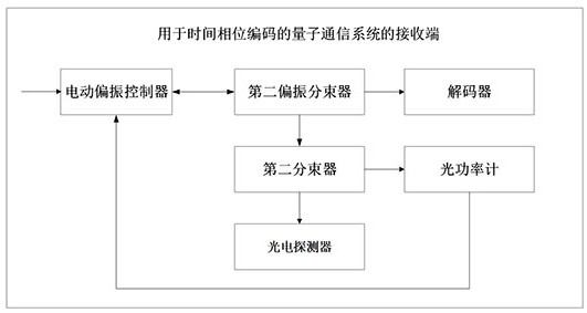
[0065] Such as figure 2 As shown, the receiving end of the quantum communication system for time-phase encoding provided by the embodiment of the present invention includes a motorized polarization controller, a second polarization beam splitter, a decoder, and a second beam splitter, wherein:

[0066] The motorized polarization controller is used to receive the beam-combined quantum light and synchronous light sent by the transmitting end and input the quantum light and synchronous light into the second polarization beam splitter;

[0067] The second polarization beam splitter is used to split the quantum light and the synchronous light and input the split quantum light to the decoder, and input the split synchronous light to the second beam splitter.

[0068] The decoder is used to decode the information to be transmitted from the quantum light.

[0069] Specifically, the decoder includes a single-photon detector, and the single-photon detector is in a gating mode, and qua...


PUM


Abstract

The invention discloses a transmitting end and a receiving end of a quantum communication system for time phase encoding, and the transmitting end comprise a seed light laser, a first beam splitter, a quantum light laser, a synchronous light laser, an encoder and a first polarization beam splitter, wherein the seed light laser is used for preparing seed light; the first beam splitter is used for splitting the seed light and inputting the two split light beams into the quantum light laser and the synchronous light laser in an injection locking mode; the quantum light laser is used for preparing pulse light consistent with the seed light in wavelength; the synchronous light laser is also used for inputting the synchronous light into the first polarization beam splitter through the second optical transmission element; the encoder is used for encoding the to-be-transmitted information according to the time sequence and the intensity of the pulsed light to obtain quantum light containing the to-be-transmitted information, so the starting time of the quantum communication system is shortened, the practicability of quantum key distribution is improved, and the code rate of the quantum communication system is improved.

Description

technical field [0001] The invention relates to the field of quantum communication, in particular to a transmitting end and a receiving end of a quantum communication system for time-phase encoding. Background technique [0002] In a quantum communication system, the sender sends quantum light to the receiver through a medium (optical fiber or free space), and the receiver uses a single-photon detector to detect the quantum light. Since the single-photon detector is in a gated mode, only the quantum light that reaches the receiver within a set period of time can be detected by the single-photon detector. The gating signal is generated by the clock signal sent by the transmitter. It is necessary to scan the gating signal with a delay to match the gating signal with the quantum light in time. After the matching is completed, the receiver performs frame synchronization to determine the gate The pulse sequence of the control signal is consistent with the pulse sequence of the q...

Claims


Application Information

Patent Timeline
Patent Type & Authority Applications(China)
IPC IPC(8): H04B10/70H04L7/00H04L9/08
CPCH04B10/70H04L7/00H04L9/0852
Inventor 陈柳平王林松王其兵范永胜万相奎
Owner QUDOOR TECH INC
Learn More