Check patentability & draft patents in minutes with Patsnap Eureka AI!

Anti-high-frequency large-signal two-wire system charge amplification circuit and implementation method thereof

A charge amplifying circuit, a technology of amplifying circuits, applied in charge amplifiers, improving amplifiers to reduce nonlinear distortion, etc., can solve the problems of clipping distortion, deep saturation, and distortion of charge amplifiers, so as to ensure no clipping distortion and ensure depth Saturate, reduce the effect of harnesses

Pending Publication Date: 2021-08-17
XIAMEN NIELL ELECTRONICS
View PDF0 Cites 2 Cited by
  • Summary
  • Abstract
  • Description
  • Claims
  • Application Information

AI Technical Summary

Problems solved by technology

[0004] 1. The traditional circuit structure requires single-ended or double-ended power supply. The power supply line, signal line and ground line need to be routed separately, and there are many requirements for the number, wiring and cost of signal lines.
[0005] 2. Due to the limitation of the electrical performance index of the output voltage and current of the operational amplifier, when the amplitude of the output voltage signal is large, it will cause nonlinear distortion due to saturation phenomenon
[0006] 3. When the sensor is affected by reasons such as temperature changes, electromagnetic interference, resonance, etc., it will inevitably produce an equivalent output charge that is much larger than the set measurement range of the charge amplifier, which will cause clipping distortion of the charge amplifier or even deep saturation.

Method used


Image

  • Anti-high-frequency large-signal two-wire system charge amplification circuit and implementation method thereof
  • Anti-high-frequency large-signal two-wire system charge amplification circuit and implementation method thereof
  • Anti-high-frequency large-signal two-wire system charge amplification circuit and implementation method thereof

Examples


Embodiment Construction

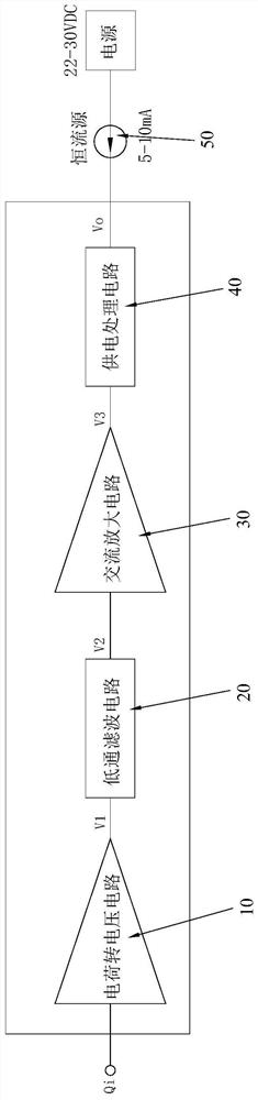
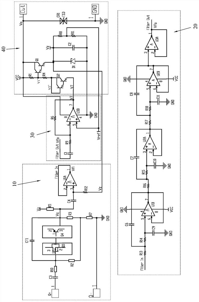
[0038] Please refer to Figure 1 to Figure 6 As shown, it shows the specific structure of a kind of anti-high-frequency large-signal two-wire charge amplifier circuit of a preferred embodiment of the present invention, including charge-to-voltage circuit 10, low-pass filter circuit 20, AC amplifier circuit 30 and Power supply processing circuit 40 .

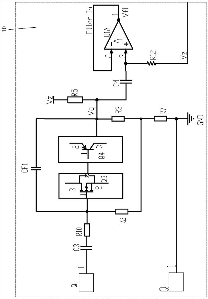
[0039] The charge-to-voltage circuit 10 adopts a charge-to-voltage circuit composed of FET-based discrete devices, and the gain is adjusted to attenuate, so that when a high frequency is input, a large signal (charge) is input, and the output is not saturated and distorted, specifically, as image 3 As shown, the charge-to-voltage circuit 10 includes a field effect transistor Q3 (N-MOSFET), a feedback capacitor CF1, a capacitor C3, a resistor R2, a resistor R3, a resistor R5, a resistor R7, a resistor R11, a resistor R12, a capacitor CF1, and a capacitor C4, operational amplifier U1A; wherein field effect transistor Q3, feedback...


PUM


Abstract

The invention discloses an anti-high-frequency large-signal two-wire system charge amplification circuit and an implementation method thereof. The anti-high-frequency large-signal two-wire system charge amplification circuit comprises a charge-to-voltage circuit, a low-pass filter circuit, an alternating-current amplification circuit and a power supply processing circuit, the low-pass filter circuit is a six-order low-pass filter circuit, the output end of the charge-to-voltage circuit is connected with the low-pass filter circuit, the low-pass filter circuit is connected with the alternating-current amplifying circuit, and the alternating-current amplifying circuit is connected with the power supply processing circuit. A constant current source two-wire system is adopted for power supply so as to reduce wire harnesses, a pre-stage charge-to-voltage circuit adopts a circuit based on a field-effect tube as a core to convert and attenuate signals so as to reduce the electrical performance index requirement of a subsequent signal processing circuit for an operational amplifier, a signal link based on signal attenuation, low-pass filtering, signal amplification and power supply processing is adopted, high-frequency large signals are suppressed under the condition that the amplitude-frequency characteristic of the required working frequency band is guaranteed, and it is guaranteed that clipping distortion and deep saturation of the signals are avoided.

Description

technical field [0001] The invention relates to the technology in the field of circuit control, in particular to an anti-high-frequency large-signal two-wire charge amplifying circuit and an implementation method thereof. Background technique [0002] Vibration measurements are required in aircraft engines or other internal combustion powered machinery. At present, in high-temperature environments, the sensors used to measure vibration mostly use piezoelectric effect type acceleration sensors with superior characteristics that output electric charges. Because the charge signal cannot be directly detected, it is necessary to use a charge amplifier to convert the charge signal into a voltage signal, so that the output voltage signal can be amplified, filtered, and calculused, and then sent to the back-end acquisition system. [0003] The existing charge-voltage signal conversion technology generally consists of an integrated op amp plus a feedback capacitor to form the main c...

Claims


Application Information

Patent Timeline
IPC IPC(8): H03F3/70H03F1/32
CPCH03F1/32H03F3/70
Inventor 陈昌鹏李坚周富强陈俊龙翁新全许静玲柯银鸿刘瑞林
Owner XIAMEN NIELL ELECTRONICS
Features
  • R&D
  • Intellectual Property
  • Life Sciences
  • Materials
  • Tech Scout
  • Unparalleled Data Quality
  • Higher Quality Content
  • 60% Fewer Hallucinations
Learn More