Control system for edible mushroom planting
A control system and technology for edible fungi, applied in the field of control systems for cultivation of edible fungi, can solve the problems of technical personnel and production workers having a great influence on the level of operation, the influence of production facilities and equipment is very large, and the freshness of edible fungi being reduced. Avoid spoilage, uniform CO2 concentration, and neat fruiting
- Summary
- Abstract
- Description
- Claims
- Application Information
AI Technical Summary
Problems solved by technology
Method used
Image
Examples
Embodiment 1
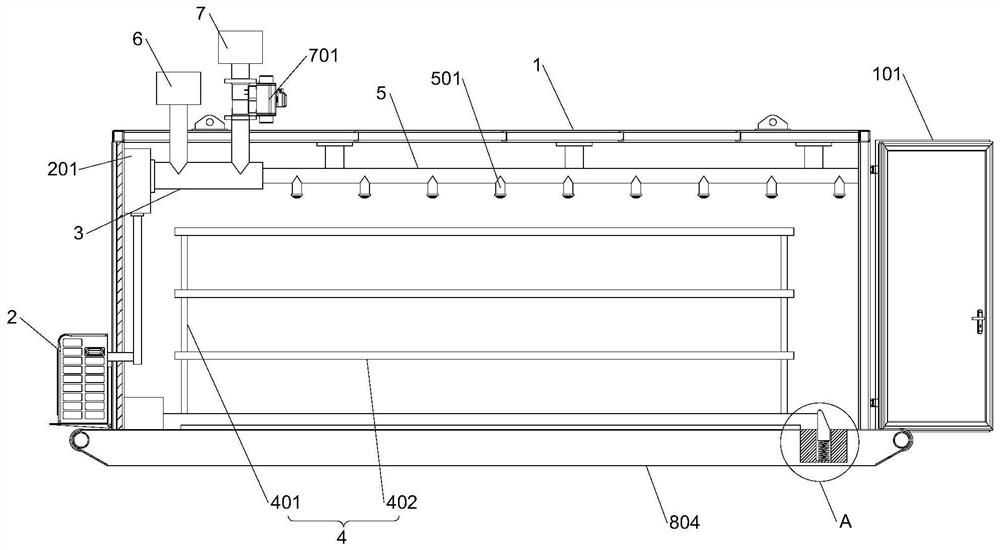
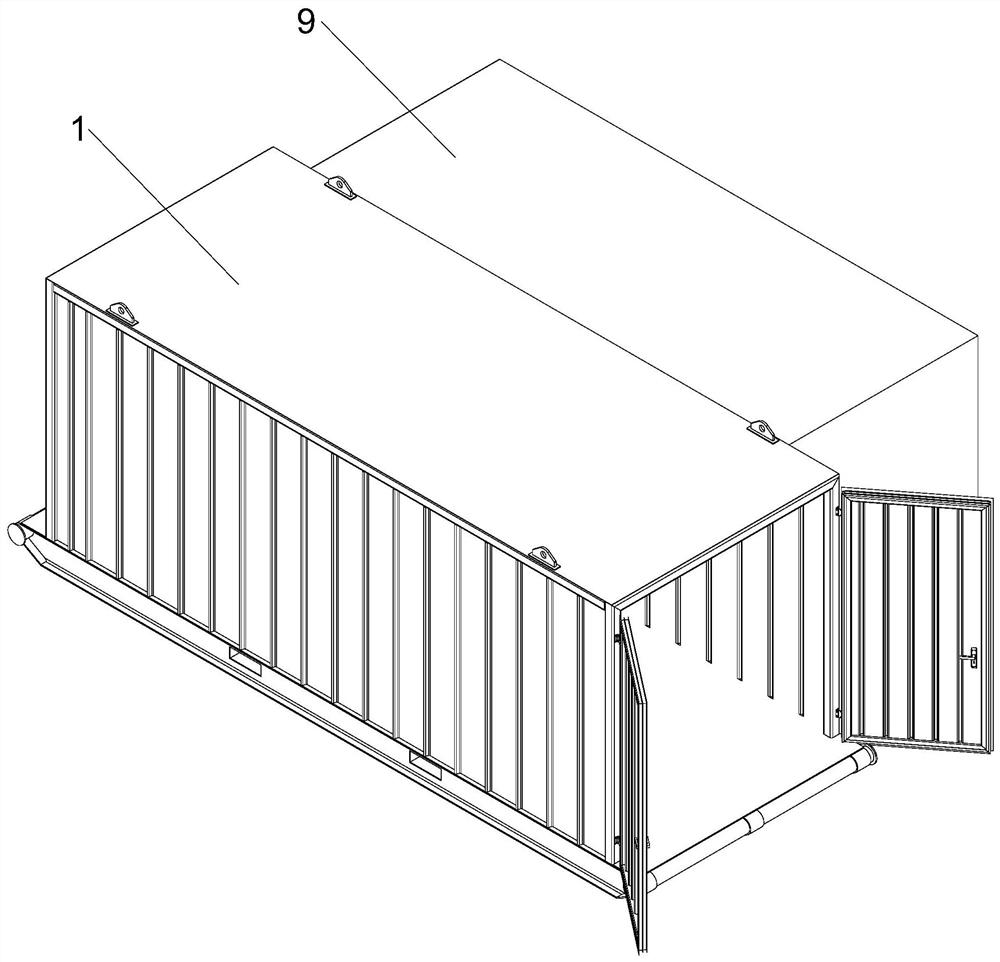
[0033] The present invention comprises box body 1, and one end of box body 1 is provided with dodge door 101, and the shelf 4 that is used for planting edible fungus is arranged inside box body 1, and shelf 4 is provided with positioning assembly 8, and box body 1 outer wall is provided with air conditioner. The outer unit 2, the inner wall of the box body 1 is provided with an air conditioner inner unit 201 interconnected with the air conditioner outer unit 2, the air outlet of the air conditioner inner unit 201 is provided with a connecting pipe 3, and the upper end of the box body 1 is also provided with a humidifier 6 and a fan 7, Both the humidifier 6 and the fan 7 communicate with the connecting pipe 3, and a solenoid valve 701 is arranged between the fan 7 and the connecting pipe 3. The connecting pipe 3 is connected with a ventilation pipe 5, and the ventilation pipe 5 is laid on the inner wall of the box body 1. The ventilation pipe 5 is provided with a plurality of ai...
Embodiment 2
[0040] This embodiment is further optimized on the basis of Embodiment 1 as follows: the dodge door 101 is made of polyurethane insulation material, the edge of the dodge door 101 is laid with a sealing strip, the dodge door 101 is equipped with an electric drive module, and the electric drive module Electrically connected with the control module. The shelf 4 includes a plurality of laminates 402 , and adjacent laminates 402 are connected to each other by support rods 401 . The side wall of the box body 1 is provided with a transparent observation window. The air vent is equipped with shutters, and the shutters are provided with a drive module, which is electrically connected to the control module. The shelf 4 is equipped with a plurality of LED light bars, the LED light bars are provided with a brightness adjustment module, and the brightness adjustment module is electrically connected with the control module.
[0041] After adopting the above technical solution: the ventil...
Embodiment 3
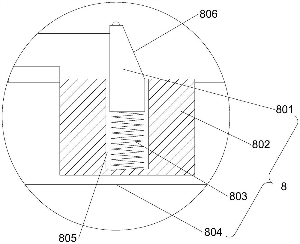
[0043] This embodiment is further optimized on the basis of Embodiment 1 as follows: the positioning assembly 8 is located at the end of the shelf 4 near the dodge door 101, and the positioning assembly 8 includes a support box 804, a positioning block 802, a limit block 801 and a positioning spring 803, the support box 804 is arranged on the bottom of the box body 1, the positioning block 802 is arranged on the bottom of the box body 1, and the upper end of the positioning block 802 is provided with a positioning groove 805, and the positioning block 802 is arranged in the positioning groove 805 and can move up and down, and the positioning block 802 runs through the lower end of the box body 1, and the positioning spring 803 is arranged between the lower end of the positioning block 802 and the bottom wall of the positioning groove 805. The upper end of the positioning block 802 is provided with a guide slope 806, and the guide slope 806 is away from the shelf 4 from top to bo...
PUM
 Abstract
Description
Claims
Application Information
 - R&D
- Intellectual Property
- Life Sciences
- Materials
- Tech Scout
- Unparalleled Data Quality
- Higher Quality Content
- 60% Fewer Hallucinations
Browse by: Latest US Patents, China's latest patents, Technical Efficacy Thesaurus, Application Domain, Technology Topic, Popular Technical Reports.
© 2025 PatSnap. All rights reserved.Legal|Privacy policy|Modern Slavery Act Transparency Statement|Sitemap|About US| Contact US: help@patsnap.com


