
A pressure oil-supplied piston oscillation cooling visual test device

A test device and piston technology, which is applied in the field of pressure-oil-supplied piston oscillating cooling visualization test device, can solve problems such as the friction pair lubrication problem and the test device dynamic balance problem, and achieve a wide range of speed coverage and easy replacement , good reliability

Active Publication Date: 2022-08-02
HUAZHONG UNIV OF SCI & TECH
View PDF36 Cites 0 Cited by
  • Summary
  • Abstract
  • Description
  • Claims
  • Application Information

AI Technical Summary

Problems solved by technology

The test devices described in patents CN110579355A and CN110207991A mainly study the form of oscillation cooling realized by telescopic sleeves and built-in oil circuits in large-scale low-speed crosshead diesel engines, and are not suitable for visual observation of pressure oil-supply piston oscillation cooling for medium-speed and high-power marine diesel engines
In addition, the above-mentioned patents generally did not consider the dynamic balance of the test device, especially how to balance the first-order and second-order reciprocating inertial forces generated by the piston movement, nor did they consider the lubrication of the main friction pairs in the test device

Method used


Image

  • A pressure oil-supplied piston oscillation cooling visual test device
  • A pressure oil-supplied piston oscillation cooling visual test device
  • A pressure oil-supplied piston oscillation cooling visual test device

Examples


specific Embodiment

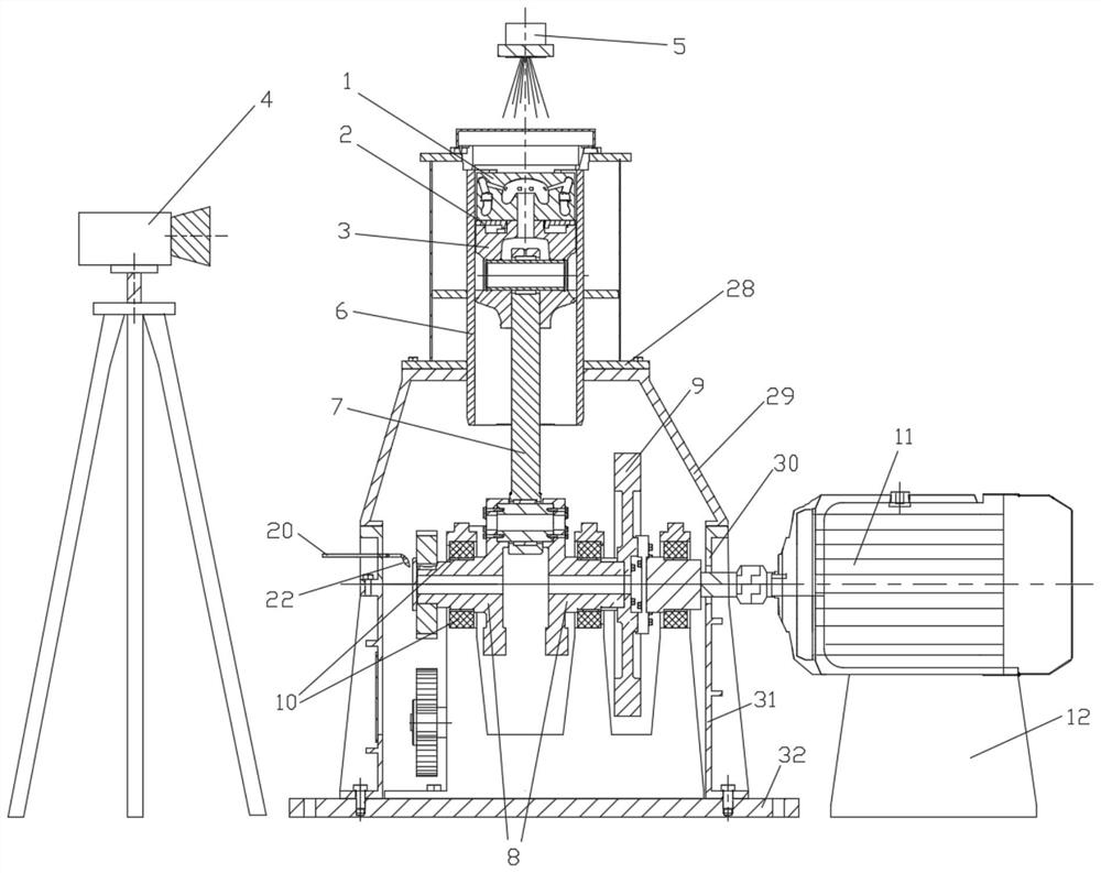
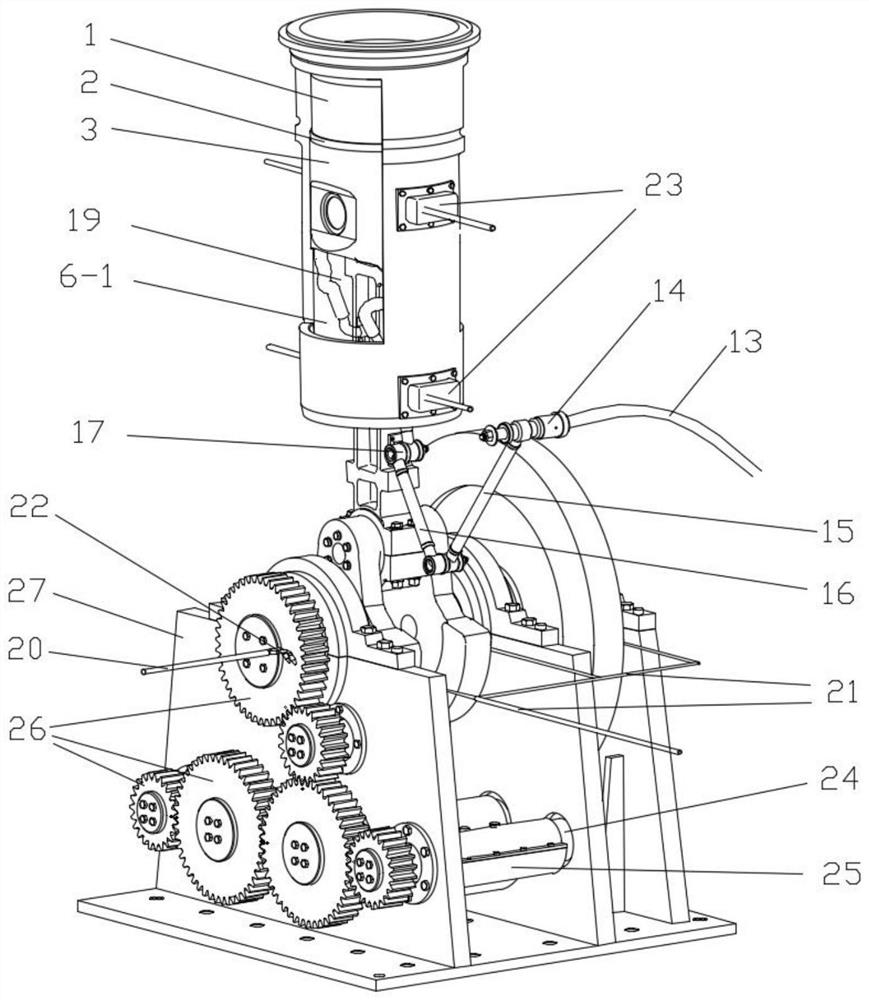
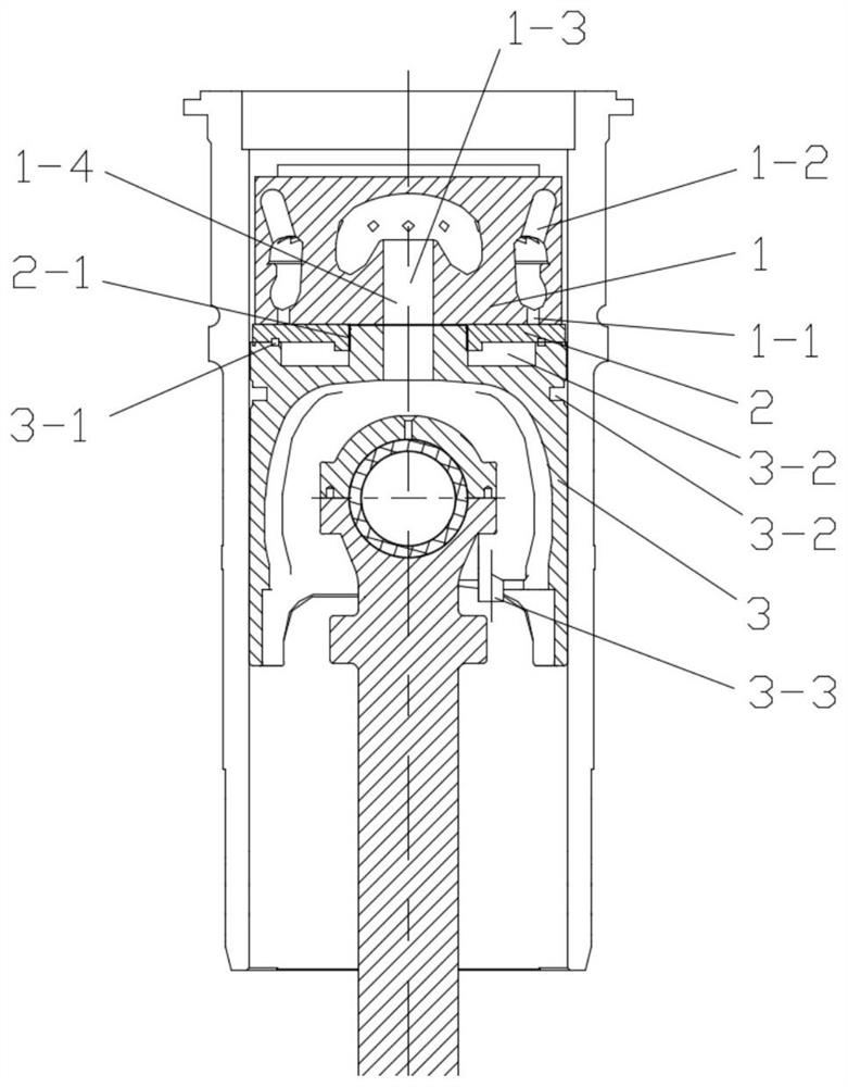
[0052] The purpose of the test is to simulate the pressure oil-supplied piston oscillating cooling process of a real marine high-power diesel engine, and obtain information such as the oscillating flow pattern and flow rate of the oil in the piston cooling chamber under different crankshaft rotation angles. The diameter of the transparent test piston is 260mm, the height is 150mm, the diameter of the guide piston is 270mm, the stroke of the piston is 330mm, the length of the connecting rod is 600mm, the radius of the crank is 165mm, the oil supply pressure of the piston cooling chamber is 4.3bar, and the oil mass flow rate is 2m 3 / h, it is necessary to observe the cooling of the transparent test piston when the transparent test piston is located at the crank angle of 0°CA, 45°CA, 90°CA, 135°CA, 180°CA, 225°CA, 270°CA, 315°CA The visual image of the oscillating flow pattern of the oil in the cavity is analyzed, and the oscillating flow, filling rate and flow rate are analyzed, ...


PUM


Abstract

The invention belongs to the field of internal combustion engines, and specifically discloses a pressure oil supply type piston oscillation cooling visualization test device, which comprises a motion mechanism, a visualized piston group, a cylinder liner, an oil supply mechanism and an observation mechanism. The motion mechanism is used to drive the visual piston group to reciprocate in the cylinder liner; the visual piston group includes the transparent test piston and the guide piston; the oil supply mechanism includes the outer oil supply pipe of the frame, the outer auxiliary connecting rod, the inner auxiliary connecting rod, and the oiling The hard pipe and the oiling hose assembly, the outer auxiliary connecting rod and the inner auxiliary connecting rod are movably connected, and there are inner oil passages in them. The oil supply mechanism is used to supply oil to the transparent test piston pressure; the observation mechanism is used to pass through the cylinder. The observation window on the sleeve takes pictures of the inside of the transparent test piston. The invention drives the movement of the visualized piston group through the motion mechanism, and cooperates with the pressure oil supply mechanism based on the auxiliary connecting rod and the observation mechanism based on the transparent test piston, so that the oscillation of the cooling oil of the marine diesel engine piston can be simulated and visualized.

Description

technical field [0001] The invention belongs to the field of internal combustion engines, and more particularly relates to a pressure oil supply type piston oscillation cooling visualization test device. Background technique [0002] Diesel engines have the advantages of strong power, good economy and high reliability. They are widely used in the fields of national defense and military industry, road transportation, construction machinery, etc., especially in the shipping industry, occupying a dominant position. With the continuous improvement of diesel engine power and strengthening degree, the failure of key components such as pistons and cylinder heads may greatly increase. In order to ensure the reliability and durability of diesel engines, higher reliability of key components is proposed. Require. [0003] As one of the core components of a diesel engine, the piston plays a vital role, converting the instantaneous thermal energy in the combustion system into mechanical...

Claims


Application Information

Patent Timeline
Patent Type & Authority Patents(China)
IPC IPC(8): G01M15/02G01M15/04G01M10/00
CPCG01M15/02G01M15/04G01M10/00
Inventor 王兆文刘柯张驰成晓北李梅
Owner HUAZHONG UNIV OF SCI & TECH
Learn More