A Balanced-Unbalanced Coupler with Arbitrary Power Split Ratio
A power division ratio and coupler technology, applied in the field of couplers, can solve the problems of physical realization processing limitations, limited power division ratio, etc.
- Summary
- Abstract
- Description
- Claims
- Application Information
AI Technical Summary
Problems solved by technology
Method used
Image

Examples
specific Embodiment
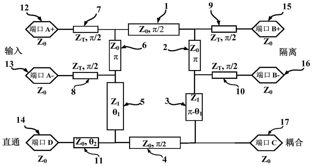
[0030] Specific embodiment: power division ratio is 15dB, Z 0 = 50 ohms, Z 1 = 35 ohms, Z T = 70.7 ohms, θ 1 = 75.4 degrees, θ 2 = 79.4 degrees.
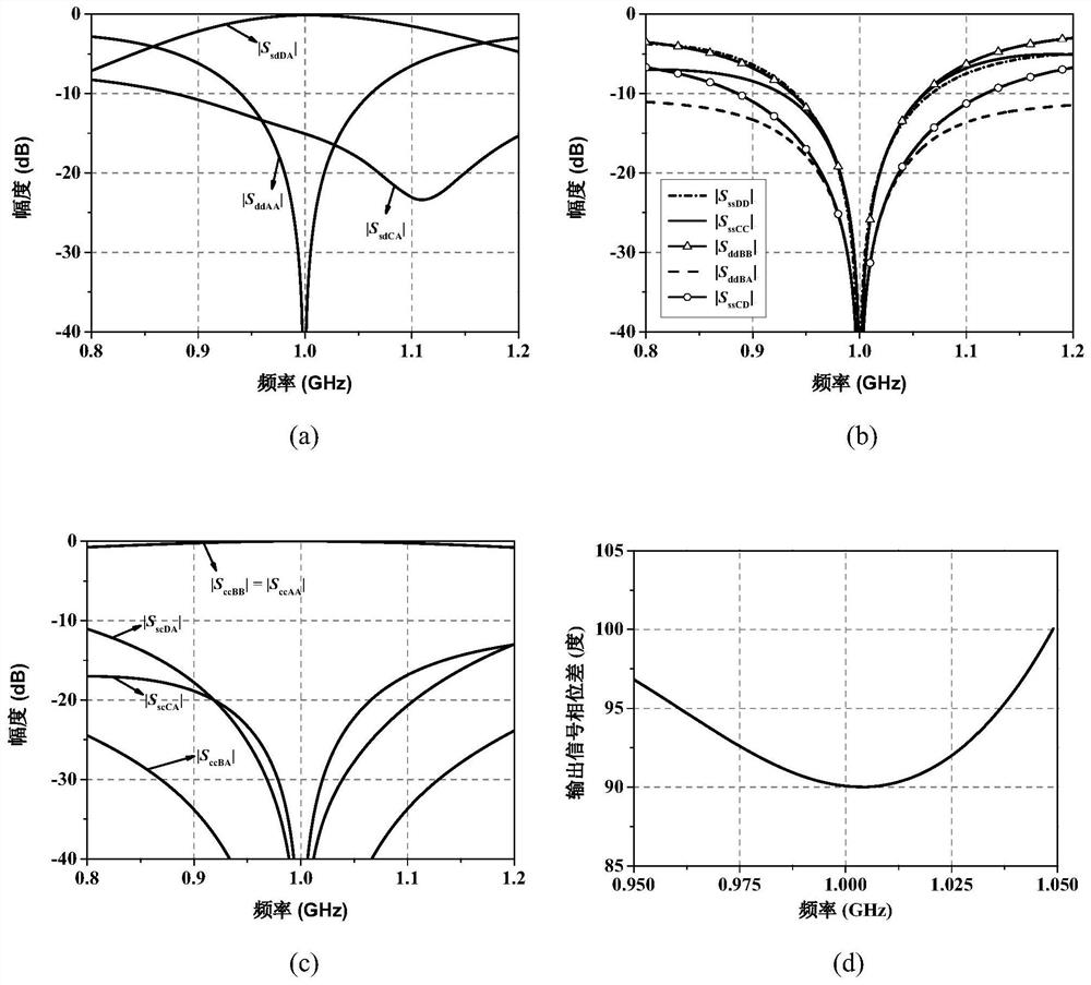
[0031] specifically, figure 2 It shows a mixed S-parameter curve of a balanced-unbalanced coupler with arbitrary power ratio in the present invention. from figure 2 (a) It can be seen that at the central operating frequency of 1.0GHz, the unbalanced signal goes through the output port D corresponding to the |S sdDA | is -0.1dB, unbalanced terminal signal coupling output port C corresponding to the |S sdCA | is -15.1dB, and the output signal power ratio between the two output ports is 15dB, which meets the design requirement of the required 15dB power division ratio. from figure 2 (b) It can be seen that at the central operating frequency of 1.0 GHz, both the balanced differential signal output port and the unbalanced signal through / coupling output port have ideal impedance matching characteristics; |S ssCD |Less than -4...
PUM
 Abstract
Description
Claims
Application Information
 - R&D
- Intellectual Property
- Life Sciences
- Materials
- Tech Scout
- Unparalleled Data Quality
- Higher Quality Content
- 60% Fewer Hallucinations
Browse by: Latest US Patents, China's latest patents, Technical Efficacy Thesaurus, Application Domain, Technology Topic, Popular Technical Reports.
© 2025 PatSnap. All rights reserved.Legal|Privacy policy|Modern Slavery Act Transparency Statement|Sitemap|About US| Contact US: help@patsnap.com