System for treating and recycling composite material

A technology of composite materials and material tanks, applied in the field of energy and chemical industry, can solve the problems of no industrial application, etc., and achieve the effect of high energy utilization rate and environmental protection of process flow

Pending Publication Date: 2021-09-07
胡进 +1
View PDF3 Cites 0 Cited by
  • Summary
  • Abstract
  • Description
  • Claims
  • Application Information

AI Technical Summary

Problems solved by technology

However, at present, various enterprises claim to add and reuse cement products such as composite material products (SMC / BMC), building panels, non-load-bearing manhole covers, sidewalk bricks, curbs and other cement products. After investigation, it is found that there is no mature industrial application.

Method used


Image

  • System for treating and recycling composite material
  • System for treating and recycling composite material
  • System for treating and recycling composite material

Examples


Embodiment 1

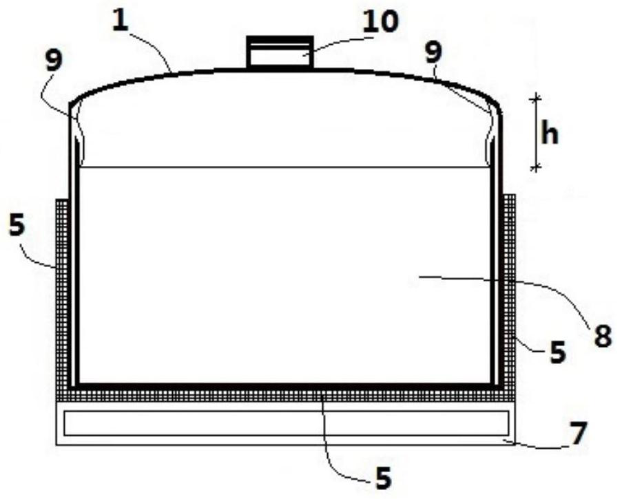
[0095] First, various composite fiber raw materials matching the length of the material trough 8 are sorted out. The composite fiber raw material is dehydrated and dried in advance. Then the raw materials are loaded into the material tank 8 and sent into the body of the thermal cracking reactor 1, and the feed door 2 of the thermal cracking reactor can be opened at 180°. The main part of the reactor body of the thermal cracking reactor 1 is a cuboid for carrying the material tank 8 . The top of the still body of the pyrolysis reactor 1 is an elliptical vault top, and its cross section is as follows: image 3 shown. Now open the high temperature resistant centrifugal induced draft fan 14 to extract the air in the still body, so that the pressure value in the still body reaches the low vacuum pressure range. Then use the flat-plate electromagnetic induction heating jacket 5 to heat the composite fiber raw material in the still body of the pyrolysis reactor 1 to 400°C-450°C in...

Embodiment 2

[0102] Because thermal cracking crude oil is a mixture of aliphatic, aromatic and polar compounds with a boiling point between about 70°C and 400°C, it is dark brown in color and strongly irritating. Therefore, it is difficult to find wider applications without purification. Firstly, the crude oil stored in the crude oil storage tank 24 is pumped into the still body of the crude oil rectification kettle 26 from the crude oil feed port 28 by an oil pump. The kettle body of the crude oil rectifying kettle 26 is a horizontal cylinder, and a radar level gauge 33 is installed on the top of the kettle. The rectification needs to gradually increase the temperature of the crude oil from normal temperature to 200°C-350°C. In this embodiment, the temperature of 290°C-300°C is used for rectification. The temperature rise of the crude oil rectification kettle 26 is provided by a high-power semi-circular electromagnetic heating jacket 31, and the temperature, time and power required for h...


PUM


Abstract

The invention discloses a system for treating and recycling a composite material, the system at least comprises an electromagnetic induction thermal cracking system, and the electromagnetic induction thermal cracking system comprises a thermal cracking reaction kettle (1) and a flat plate type electromagnetic induction heating sleeve (5) arranged on the outer side of the kettle body of the thermal cracking reaction kettle (1), the dehydrated and dried recycled composite material is put into a material tank (8) in the thermal cracking reaction kettle (1), the recycled composite material is heated to 400-450 DEG C through the flat plate type electromagnetic induction heating sleeve (5) in a low vacuum environment in the kettle body of the thermal cracking reaction kettle (1), and solid residues and thermal cracking gas are obtained after the recycled composite material is subjected to thermal cracking reaction; the solid residues are subjected to fiber and residual carbon separation and fiber surface treatment to obtain regenerated fibers, and the thermal cracking gas is subjected to catalysis, gas / water separation and heat exchange treatment to obtain crude oil and non-condensable gas. The system is environment-friendly and efficient, and long fibers in the composite material can be recycled.

Description

technical field [0001] The invention relates to the technical field of energy and chemical industry, in particular to a system for processing recycled composite materials. Background technique [0002] Composite materials are preferred in many engineering applications due to their durability and superior strength. Proper waste treatment and recycling at the end of composite material life is a must. Many current and future waste management and environmental regulations will require the proper recovery and recycling of engineered materials from products that have reached their end of life, such as automobiles, wind turbines and aircraft. Although many technologies have been developed such as mechanical recycling, thermal recycling and chemical recycling; they are on the verge of full commercialization. Extensive research and development is ongoing to develop better recyclable composite materials and composite recycling technologies. This will contribute to the sustainable d...

Claims


Application Information

Patent Timeline
Patent Type & Authority Applications(China)
IPC IPC(8): C10B53/02C10G1/00H05B6/10
CPCC10B53/02C10G1/002C10G1/00H05B6/10Y02E50/10
Inventor 胡进
Owner 胡进
Why Eureka
Try Eureka