
Transcritical carbon dioxide heat pump driven system for preparing ice slurry through rotary wheel dehumidification and evaporation

A carbon dioxide and rotary dehumidification technology, which is used in ice making, ice making, evaporator/condenser, etc. It can solve the problems of high concentration of dehumidification solution, ice blockage of evaporator pipes, and large mechanical power consumption.

Active Publication Date: 2021-09-10
南京东达智慧环境能源研究院有限公司
View PDF1 Cites 0 Cited by
  • Summary
  • Abstract
  • Description
  • Claims
  • Application Information

AI Technical Summary

Problems solved by technology

[0003] In the current method of producing liquid ice, the supercooling method is prone to ice blockage in the evaporator pipe due to the instability of the supercooled water; the mechanical scraper method is the most widely commercialized flow ice State ice preparation method, but it needs to consume a lot of extra mechanical power; the traditional vacuum method to produce liquid ice has a large vacuum pump energy consumption, and on this basis, the method of producing liquid ice by evaporation of solution dehumidification, then The concentration of the dehumidification solution is required to be high, and the solution dehumidification system is complicated, which increases the cost of making liquid ice

Method used


Image

  • Transcritical carbon dioxide heat pump driven system for preparing ice slurry through rotary wheel dehumidification and evaporation

Examples


Embodiment Construction

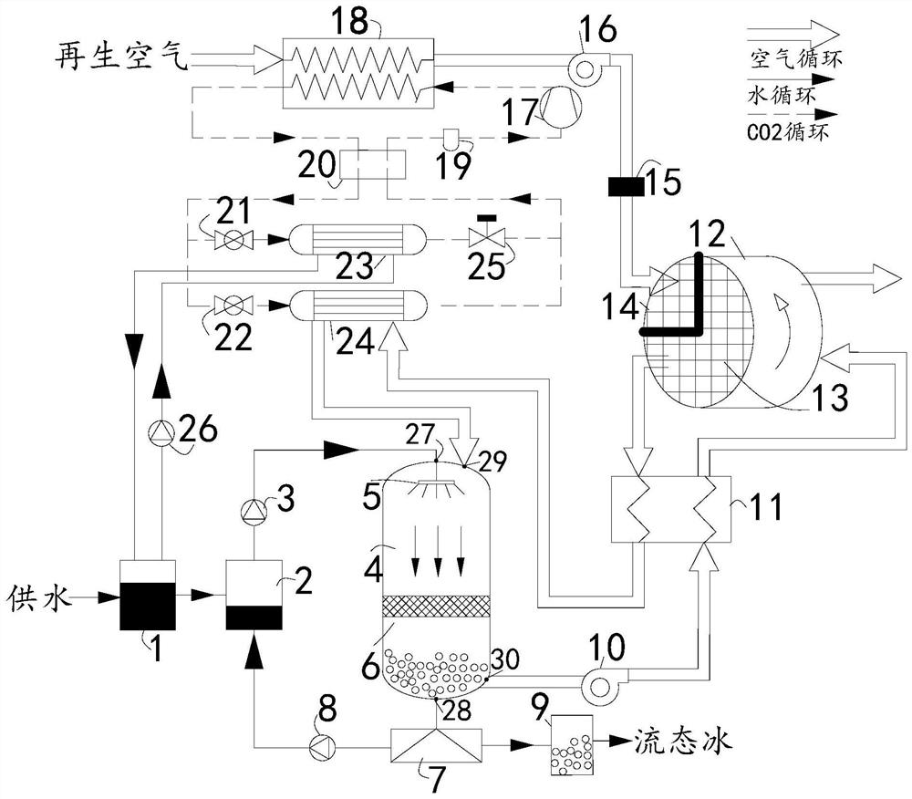
[0022] Such as figure 1 As shown, a system schematic diagram of a transcritical carbon dioxide heat pump-driven rotary dehumidification and evaporation system for producing liquid ice, in this embodiment, includes a heat pump precooling and heat recovery system, an evaporative ice making system, and a rotary dehumidification system ;

[0023]The heat pump pre-cooling and heat recovery system uses carbon dioxide as the circulating working medium. On the one hand, it pre-cools the circulating water and circulating air; on the other hand, it heats the regeneration air through heat recovery at a transcritical high temperature; The system includes a water storage tank 1, a compressor 17, a gas cooler 18, a gas-liquid separator 19, a regenerator 20, a first throttle valve 21, a second throttle valve 22, a water-cooled evaporator 23, an air-cooled evaporator 24, Pressure regulating valve 25 and circulating water pump 26. First, the refrigerant carbon dioxide is compressed by the co...


PUM


Abstract

The invention provides a transcritical carbon dioxide heat pump driven system for preparing ice slurry through rotary wheel dehumidification and evaporation. The transcritical carbon dioxide heat pump driven system comprises a heat pump pre-cooling and heat recovery system, an evaporation ice-making system and a rotary wheel dehumidification system. The heat pump pre-cooling and heat recovery system takes carbon dioxide as a cycle, on one hand, circulating water and circulating air are pre-cooled and cooled, and on the other hand, regenerated air is heated through heat recovery at transcritical high temperature. The evaporation ice-making system takes water as a cycle, and pre-cooled circulating water enters an evaporation ice-making chamber and is evaporated and cooled in low-moisture-content air to generate the ice slurry. The rotary wheel dehumidification system takes air as a cycle, wet air from the evaporation ice-making chamber passes through a dehumidification area to be dehumidified to obtain low-moisture-content air, and then the low-moisture-content air is sent back; the dehumidification capacity of the dehumidification area is recovered through heating of the regenerated air. By means of the transcritical carbon dioxide heat pump driven system, the ice making energy consumption is greatly reduced through rotary wheel dehumidification, meanwhile, high-temperature heat recovery is carried out by using the carbon dioxide as a circulating heat pump, and the system is a novel energy-saving, efficient and environment-friendly ice slurry making system.

Description

technical field [0001] The invention relates to a system for producing fluid ice, in particular to a system for producing fluid ice by dehumidifying and evaporating a runner driven by a transcritical carbon dioxide heat pump. Background technique [0002] With the development of economy and society, the problem of energy shortage has gradually become prominent, and the energy consumption of refrigeration equipment, including air-conditioning systems, has aroused widespread social concern. As one of the most important energy-saving technologies at present, ice storage is an effective method to "shift peaks and fill valleys" of electricity and solve peak power shortages. As a good medium for ice storage, liquid ice is also widely used in building air conditioning, large-scale district cooling, industrial production, food preservation, transportation, ocean fishing, aquaculture, etc. due to its good thermophysical properties. healthcare and other fields. On the other hand, th...

Claims


Application Information

Patent Timeline
IPC IPC(8): F25C1/00F25B41/40F25B41/20F25B40/06F25B43/00F25B39/00F25B9/00
CPCF25C1/00F25B41/40F25B41/20F25B40/06F25B43/00F25B39/00F25B9/008Y02P60/85
Inventor 岳峥张小松赵善国
Owner 南京东达智慧环境能源研究院有限公司
Learn More