Narrow-gap laser-TIG electric arc composite welding device and welding method

A hybrid welding, narrow gap technology, applied in the field of welding manufacturing, can solve the problems of many welding passes, low TIG welding speed, low welding wire deposition efficiency, etc.

Pending Publication Date: 2021-09-14
HARBIN WELDING INST LTD
View PDF0 Cites 3 Cited by
  • Summary
  • Abstract
  • Description
  • Claims
  • Application Information

AI Technical Summary

Problems solved by technology

However, as a kind of arc welding, TIG welding has the common shortcomings of arc welding: the welding speed of TIG and its filler wire welding process is low, generally 0.1m / min-0.2m / min, and the welding wire deposition efficiency Low, especially for the welding of medium-thick structural parts, more welding passes are required, resulting in low welding efficiency, and due to the low TIG welding speed, the heat input to the joint is large, which easily leads to large welding deformation. At the same time, it causes a series of shortcomings such as coarse structure of welded joints, wide heat-affected zone, and weakened performance.
Although the laser-TIG arc hybrid welding method has advantages in many aspects, with the continuous improvement of product quality and production efficiency requirements, especially in the welding of large-thickness materials, limited by the size of the welding torch, in order to ensure the accessibility of the welding torch , The groove area is large, resulting in a large amount of metal filling, which greatly reduces the welding efficiency of the product, consumes a lot of welding consumables, and has a high production cost. At the same time, its welding deformation is serious
In addition, there are multi-layer and multi-channel interlayer and side wall fusion technical problems in the current welding, and the welding quality of the product is greatly affected.

Method used


Image

  • Narrow-gap laser-TIG electric arc composite welding device and welding method
  • Narrow-gap laser-TIG electric arc composite welding device and welding method
  • Narrow-gap laser-TIG electric arc composite welding device and welding method

Examples


Embodiment Construction

[0040]It should be noted that, in the case of no conflict, the embodiments of the present invention and the features in the embodiments can be combined with each other.

[0041] The present invention will be described in detail below with reference to the accompanying drawings and examples.

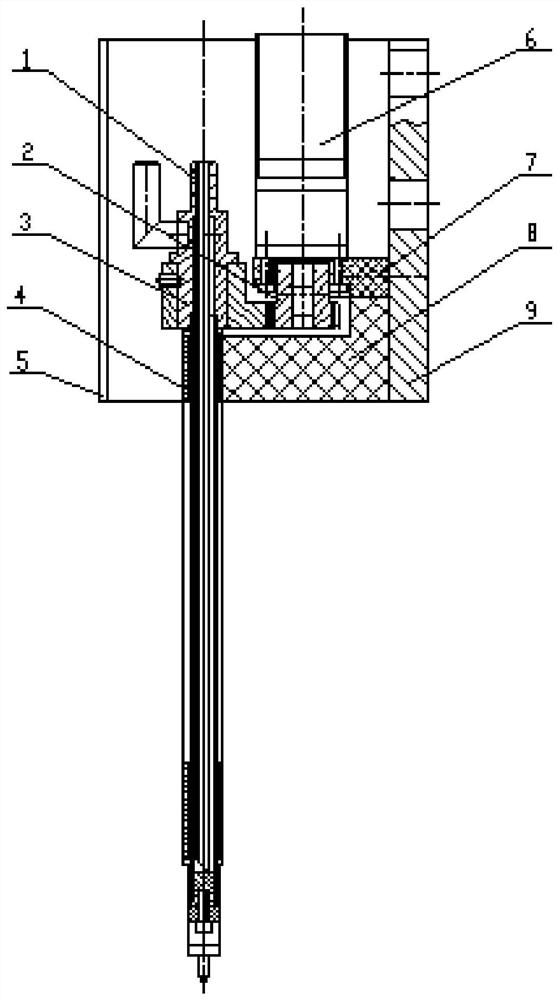
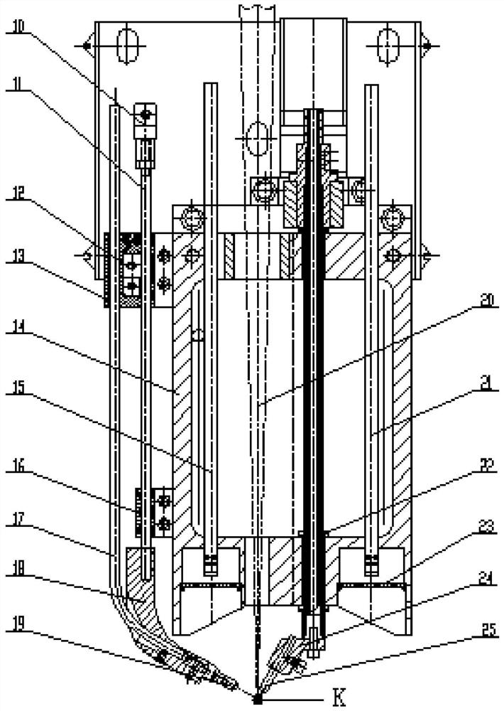
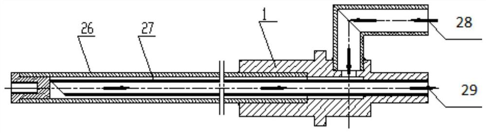
[0042] Such as Figure 1-Figure 3 As shown, a narrow gap laser-TIG arc hybrid welding device includes a welding torch body 14, a swing welding torch assembly A, a welding wire feeding heating assembly B and an air supply assembly, and the swing welding torch assembly includes a welding torch shaft 1, a stepping motor 6 , large gear 3, pinion 2, upper insulating sleeve 4, lower insulating sleeve 16, tungsten pole clip 24 and tungsten pole 25, the described stepper motor 6 is installed on the motor connecting seat 7, and the described pinion gear 2 is installed On the output shaft of the stepper motor 6, the large gear 3 is installed on the welding torch shaft 1, the pinion 2 and the large...


PUM

PropertyMeasurementUnit
thicknessaaaaaaaaaa
diameteraaaaaaaaaa

Abstract

The invention provides a narrow-gap laser-TIG electric arc composite welding device and a welding method. The welding device comprises a welding gun body, a swing welding gun assembly, a welding wire feeding and heating assembly and an air feeding assembly, wherein the swing welding gun assembly comprises a welding gun rotating shaft, a stepping motor, a large gear, a pinion, an upper insulation sleeve, a lower insulation sleeve, a tungsten electrode clamp and a tungsten electrode; the stepping motor is installed on a motor connecting base; the pinion is installed on an output shaft of the stepping motor; the large gear is installed on the welding gun rotating shaft; the pinion is meshed with the large gear; the welding gun rotating shaft is installed and positioned on the welding gun body through the upper insulation sleeve and the lower insulation sleeve; the tungsten electrode is installed at the tail end of the welding gun rotating shaft through the tungsten electrode clamp; the welding wire feeding and heating assembly is used for feeding and heating wires; the welding arc and the focus point of the laser beam jointly act on the same welding pool area; and the air feeding assembly conveys a welding protection gas to a welding arc area. The product quality and the welding efficiency are improved, the welding cost is reduced, the welding deformation is reduced, and the weld width is accurately controlled.

Description

technical field [0001] The invention belongs to the technical field of welding manufacturing, and in particular relates to a narrow gap laser-TIG arc hybrid welding device and a welding method. Background technique [0002] As one of the traditional arc welding technologies, tungsten inert gas welding (TIG) has the advantages of good arc stability, high reliability, high-quality welding, and excellent weld seams. , marine engineering and many other fields have a wide range of applications. However, as a kind of arc welding, TIG welding has the common shortcomings of arc welding: the welding speed of TIG and its filler wire welding process is low, generally 0.1m / min-0.2m / min, and the welding wire deposition efficiency Low, especially for the welding of medium-thick structural parts, more welding passes are required, resulting in low welding efficiency, and due to the low TIG welding speed, the heat input to the joint is large, which easily leads to large welding deformation....

Claims


Application Information

Patent Timeline
Patent Type & Authority Applications(China)
IPC IPC(8): B23K26/348B23K26/70B23K26/60
CPCB23K26/348B23K26/702B23K26/70B23K26/60
Inventor 滕彬张焱黄瑞生徐锴费大奎蒋宝武鹏博梁晓梅李小宇曹浩
Owner HARBIN WELDING INST LTD
Why Eureka
Try Eureka