Fabrication method of Gan-based hemt device based on pre-via etching
A device and pre-pass technology, applied in the field of semiconductor design and manufacturing, can solve the problems of yield reduction, high manufacturing and equipment costs, and achieve the effects of improving yield, saving production equipment and costs, and avoiding device damage.
- Summary
- Abstract
- Description
- Claims
- Application Information
AI Technical Summary
Problems solved by technology
Method used
Image
Examples
Embodiment 1
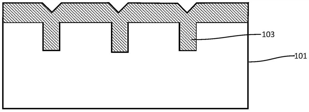
[0053] Such as Figure 1 to Figure 10 As shown, this embodiment provides a method for preparing a GaN-based HEMT device based on pre-via etching. The device may be a radio frequency device, for example. The preparation method includes the steps:
[0054] Such as Figure 1 ~ Figure 2 As shown, step 1) is first performed to provide a substrate 101, the substrate 101 includes a first main surface and a second main surface opposite, and a deep groove is etched in the first main surface of the substrate 101 Groove 102, the deep trench 102 is set corresponding to the source of the GaN-based HEMT device.
[0055] As an example, the substrate 101 includes one of a silicon-based substrate, a silicon carbide substrate, a gallium nitride substrate, and a sapphire substrate. In this embodiment, the substrate 101 is selected as a semi-insulating silicon substrate, which is used as the substrate required for the growth of the epitaxial layer structure of the GaN-based HEMT device.
[0056...
Embodiment 2
[0079] Such as Figure 11 As shown, this embodiment provides a method for preparing a GaN-based HEMT device, the basic steps and basic structure of which are as in Embodiment 1, wherein the difference from Embodiment 1 is that the substrate is selected as a silicon carbide substrate 201.
Embodiment 3
[0081] Such as Figure 12 As shown, this embodiment provides a method for preparing a GaN-based HEMT device, the basic steps of which are as in Embodiment 1, wherein the difference from Embodiment 1 lies in: step 2) the filling of the deep trench 102 The sacrificial dielectric layer 103 includes holes 301 inside the sacrificial dielectric layer 103 . In this embodiment, the surface of the substrate 101 is required to be a flat surface without depressions after the subsequent planarization process. On the one hand, the present application can allow the sacrificial dielectric layer 103 to contain holes 301, so the deposition requirements of the sacrificial dielectric layer 103 can be reduced, and the process window of the sacrificial dielectric layer 103 can be greatly widened. On the other hand, the sacrificial dielectric layer 103 contains The hole 301 can improve the efficiency of the subsequent selective removal of the sacrificial dielectric layer 103 , thereby reducing the ...
PUM
 Abstract
Description
Claims
Application Information
 - R&D
- Intellectual Property
- Life Sciences
- Materials
- Tech Scout
- Unparalleled Data Quality
- Higher Quality Content
- 60% Fewer Hallucinations
Browse by: Latest US Patents, China's latest patents, Technical Efficacy Thesaurus, Application Domain, Technology Topic, Popular Technical Reports.
© 2025 PatSnap. All rights reserved.Legal|Privacy policy|Modern Slavery Act Transparency Statement|Sitemap|About US| Contact US: help@patsnap.com


