Welding method for heat pipe radiator fins based on scanning galvanometer laser welding

A heat pipe radiator, laser welding technology, applied in laser welding equipment, welding equipment, resistance welding equipment and other directions, can solve the problems of incomplete infiltration, high laser welding power and low absorption rate of aluminum alloy fins, and reduce porosity. , avoid insufficient infiltration, improve the effect of absorption rate

Pending Publication Date: 2021-10-22
武汉光谷机电科技有限公司
View PDF10 Cites 1 Cited by
  • Summary
  • Abstract
  • Description
  • Claims
  • Application Information

AI Technical Summary

Problems solved by technology

[0005] The main purpose of the present invention is to provide a welding method based on scanning galvanometer laser welding of heat pipe radiator fins, aiming to solve the incomplete wetting existing when welding heat pipe radiator heat conduction substrate and fins by reflow soldering and high frequency induction heating , porosity and copper alloy, aluminum alloy fin laser welding power, low absorption rate and other issues

Method used


Image

  • Welding method for heat pipe radiator fins based on scanning galvanometer laser welding
  • Welding method for heat pipe radiator fins based on scanning galvanometer laser welding
  • Welding method for heat pipe radiator fins based on scanning galvanometer laser welding

Examples


Embodiment 1

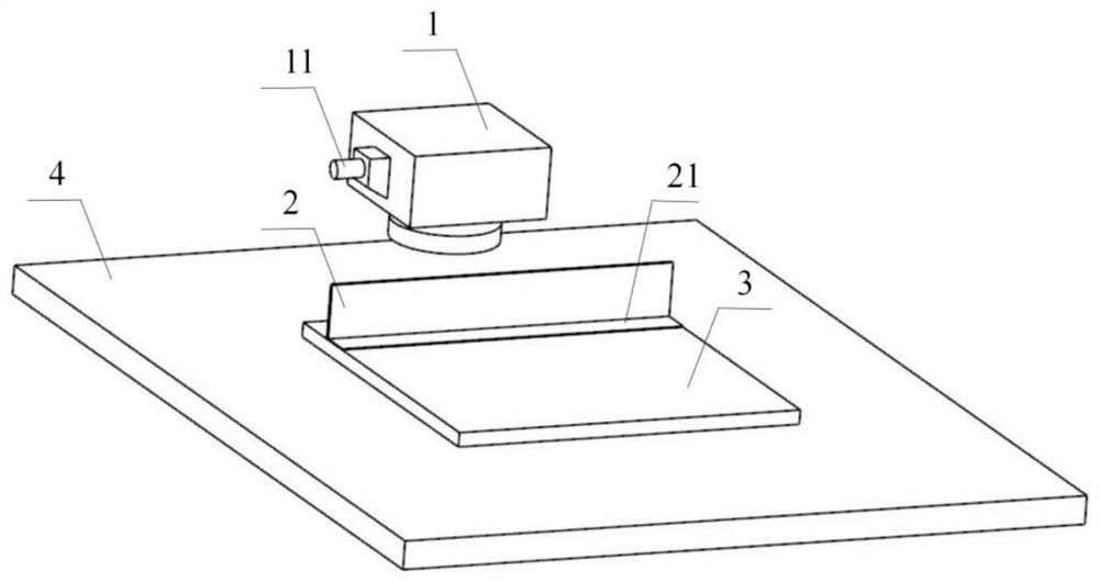
[0049] Such as Figure 4 As shown, the heat conduction substrate 3 of the heat pipe radiator is 120mm long, 90mm wide, and 4mm thick;

[0050] When utilizing the welding method of the present invention, specifically comprise the following steps:

[0051] The first step: the welding surface 21 of the L-shaped fin 2 to be welded is subjected to shot blasting, using irregularly shaped ceramic projectiles with a particle size of 0.05 mm, and the shot peening pressure is 0.1 MPa, and the surface roughness of the obtained fins is at Ra10 - between Ra20;

[0052] Step 2: Place the shot-peened L-shaped fins 2 on the area to be welded on the heat conduction substrate 3 of the heat pipe radiator, adjust the power of the blue laser to 200W, the laser spot diameter to 50μm, and the laser wavelength to 450nm. The beginning and end of the welding surface 21 of the shaped fin 2 are pre-fixed by laser spot welding;

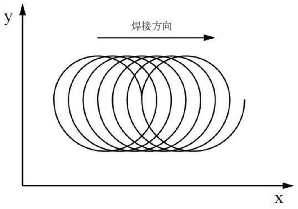
[0053] Step 3: Generate a welding path based on the welding surface 21 of...

Embodiment 2

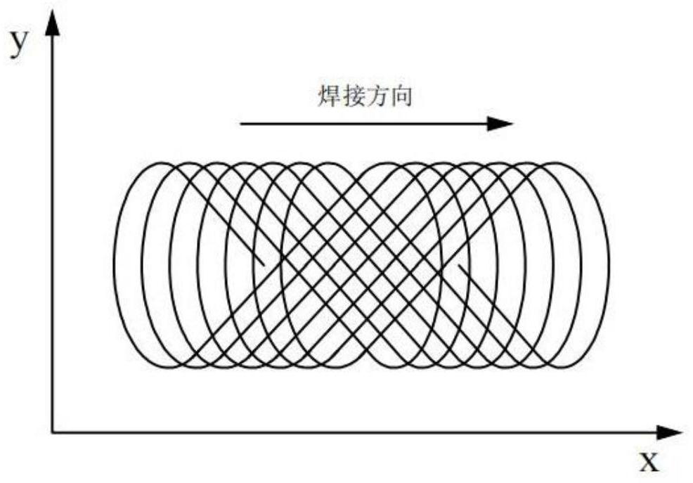
[0056] Such as Figure 5 As shown, the heat-conducting substrate 3 of the heat pipe radiator is 90mm long, 100mm wide, and 4mm thick;

[0057] When utilizing the welding method of the present invention, specifically comprise the following steps:

[0058] The first step: the welding surface 21 of the L-shaped fin 2 to be welded is subjected to shot peening treatment, and irregular-shaped cast steel projectiles with a particle size of 0.1 mm are used, and the shot peening pressure is 0.15 MPa. The surface roughness of the obtained fin is at Between Ra10-Ra20;

[0059] Step 2: Place the shot-peened L-shaped fins 2 on the area to be welded on the heat conduction substrate 3 of the heat pipe radiator, adjust the power of the blue laser to 150W, the laser spot diameter to 40μm, and the laser wavelength to 430nm. The beginning and end of the welding surface 21 of the shaped fin 2 are pre-fixed by laser spot welding;

[0060] Step 3: Generate a welding path based on the welding sur...


PUM

PropertyMeasurementUnit
Diameteraaaaaaaaaa
Laser poweraaaaaaaaaa
Laser wavelengthaaaaaaaaaa

Abstract

The invention discloses a welding method for heat pipe radiator fins based on scanning galvanometer laser welding. The welding method comprises the following steps that S1, shot blasting treatment is conducted on welding faces of the L-shaped fins to be welded; S2, spot welding and pre-fixing are conducted on the L-shaped fins subjected to shot blasting and a heat conduction substrate of a heat pipe radiator; and S3, a welding path is generated based on the welding faces of the L-shaped fins, a laser galvanometer scanning mode is set, the power of a blue laser is adjusted, welding is started from one sides of the welding faces of the L-shaped fins and finished on the other sides of the welding faces of the L-shaped fins, the positions of the L-shaped fins are kept fixed in the welding process, and a laser galvanometer moves along a movement path at the set speed so that welding of the current L-shaped fins can be completed. According to the welding method, the problems of incomplete infiltration, air holes, large laser welding power of copper alloy and aluminum alloy fins, low absorption rate and the like existing when the heat conduction substrate and the fins of the heat pipe radiator are welded through reflow soldering and high-frequency induction heating at present can be solved.

Description

technical field [0001] The invention relates to the technical field of heat pipe radiator welding, in particular to a welding method for laser welding heat pipe radiator fins based on a scanning galvanometer. Background technique [0002] The operating temperature of semiconductor integrated circuits is an important factor affecting its stability, and with the continuous improvement of the integration of semiconductor circuits, the heat production per unit area is also rising, which puts higher demands on the heat dissipation performance of radiators. Require. The unique phase-change heat dissipation method of the heat pipe radiator enables it to achieve lower thermal resistance and higher heat dissipation efficiency than the solid radiator, so it is widely used in the cooling system of integrated circuits. [0003] At present, the commonly used heat pipe radiator structure on the market mainly includes three parts: heat pipe, heat conduction substrate and fins. Among them,...

Claims


Application Information

Patent Timeline
IPC IPC(8): B23K26/082B23K26/21B23K26/60B23K11/11B24C1/06
CPCB23K26/082B23K26/21B23K26/60B23K11/11B24C1/06
Inventor 廖小文余圣甫广爱清
Owner 武汉光谷机电科技有限公司
Why Eureka
Try Eureka