Heat energy and solar energy linkage sludge drying treatment equipment and process

A technology for drying sludge and treatment equipment, which is applied in the directions of sludge treatment, dehydration/drying/thickened sludge treatment, water/sludge/sewage treatment, etc. It can solve the problems of technology that needs to be perfected, short service life of equipment, and pressing time. Long and other problems, to achieve the effect of easy management and orderly consumption, low degree of secondary pollution, and large volume of water separation

Pending Publication Date: 2021-10-22
绍兴市上虞区供水有限公司
View PDF6 Cites 0 Cited by
  • Summary
  • Abstract
  • Description
  • Claims
  • Application Information

AI Technical Summary

Problems solved by technology

[0003] However, there is still a lack of deep dehydration equipment with low energy consumption, low additive dosage, large production capacity and continuous treatment of sludge.
The plate and frame deep dehydration processors currently on the market can meet the relevant requirements in terms of dehydration, but their pressing time is long, they cannot discharge continuously, the processing capacity of a single device is small, the service life of the equipment is short, and the technology needs to be improved, etc. Disadvantages limit its further promotion and use

Method used


Image

  • Heat energy and solar energy linkage sludge drying treatment equipment and process
  • Heat energy and solar energy linkage sludge drying treatment equipment and process

Examples


Embodiment Construction

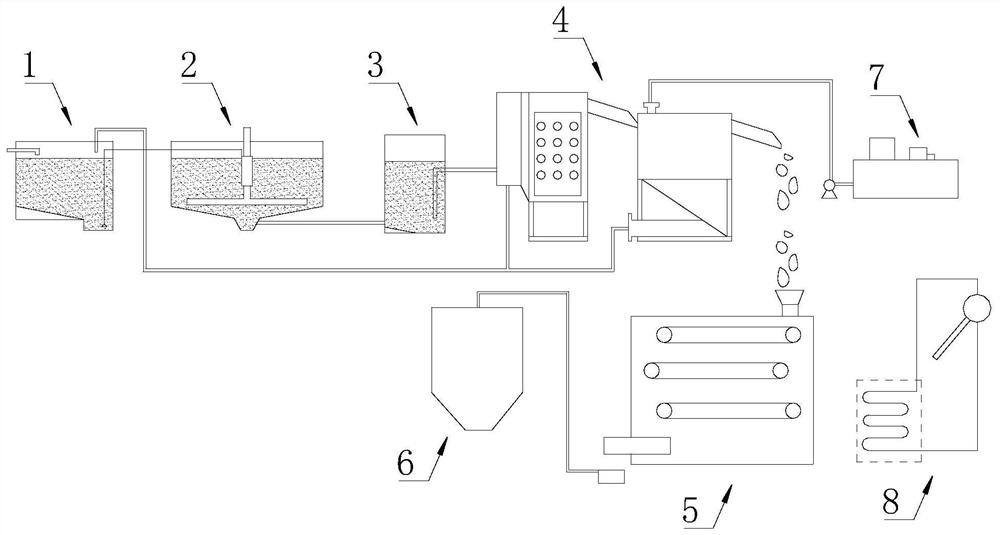
[0049] see figure 1 The thermal energy and solar energy linkage drying sludge treatment equipment, including the sludge discharge tank 1, the sludge concentration tank 2, the homogenization tank 3, the dehydrator 4, the low temperature drying machine 5, the drying sludge silo 6, the flocculation Agent machine 7 and solar auxiliary heat machine 8.

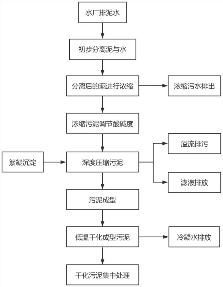
[0050] The sludge discharge tank 1 preliminarily precipitates and separates the sludge in the tap water. The upper tap water can be used for water supply, and the bottom sludge is separated from the upper tap water for dehydration treatment. The water content of the bottom sludge is between 99.6% and 99.2%. The supernatant from sludge discharge tank 1 is collected and pumped to the municipal sewage pipe network outside the plant.

[0051] The sludge concentration tank 2 concentrates the sludge that has been preliminarily precipitated and separated. Sediment or centrifuge the bottom sludge separated from tap water to reduce the wate...


PUM


Abstract

The invention discloses heat energy and solar energy linkage drying sludge treatment equipment and process, and belongs to the technical field of water supply cleaning. The heat energy and solar energy linkage drying sludge treatment equipment comprises a sludge discharge tank, a sludge concentration tank, a homogenizing tank, a dehydrator, a low-temperature drying machine and a dried sludge bin which are distributed in sequence, wherein the sludge discharge tank carries out primary precipitation and separation on the sludge in tap water;the sludge concentration tank makes the sludge subjected to primary precipitation and separation concentrated; thehomogenizing tank adjusts the pH value of the concentrated sludge; the dehydrator makes the sludge after pH adjustment mechanically dewatered; thelow-temperature drying machine makes themechanically dewatered sludge formed and dried and dewatered at low temperature; the dried sludge is collected by the dried sludge bin and is to be delivered and treated; the sludge with the original water content of 99.6%-99.2% is prepared into a sludge cake with the water content of 8%-12%; and the water separation volume of the sludge is large, the energy consumption of the device is low, the secondary pollution degree of the sludge is low, and the sludge is subjected to centralized recovery treatment and is convenient to manage and orderly consume.

Description

technical field [0001] The invention belongs to the technical field of water supply cleaning, and more specifically relates to thermal energy and solar energy linkage drying sludge treatment equipment and technology. Background technique [0002] In order to facilitate the further treatment and disposal of sludge, the Ministry of Environmental Protection Document No. 157 "Notice on Strengthening the Prevention and Control of Sludge Pollution in Urban Sewage Treatment Plants" stipulates that if the sludge is transported out of the industry for the purpose of storage (that is, without treatment and disposal), the sludge must be transported The mud is dehydrated to a moisture content below 50%. [0003] However, there is still a lack of deep dehydration equipment with low energy consumption, low additive dosage, large production capacity and continuous treatment of sludge. The plate and frame deep dehydration processors currently on the market can meet the relevant requireme...

Claims


Application Information

Patent Timeline
IPC IPC(8): C02F11/121C02F11/127C02F11/00C02F11/14C02F11/13H02S20/32H02S40/22F24S20/30
CPCC02F11/121C02F11/127C02F11/00C02F11/004C02F11/14C02F11/13H02S20/32H02S40/22F24S20/30Y02E10/40Y02E10/52
Inventor 倪炯陈胜阳潘骏孙添城
Owner 绍兴市上虞区供水有限公司
Why Eureka
Try Eureka