Planar flying probe testing device
A flying probe testing, flat technology, applied in the field of flying probe testing, can solve problems such as probe damage to the board, avoid extrusion collision, meet the requirements of appearance audit, and protect the board.
- Summary
- Abstract
- Description
- Claims
- Application Information
AI Technical Summary
Problems solved by technology
Method used
Image
Examples
Embodiment 1
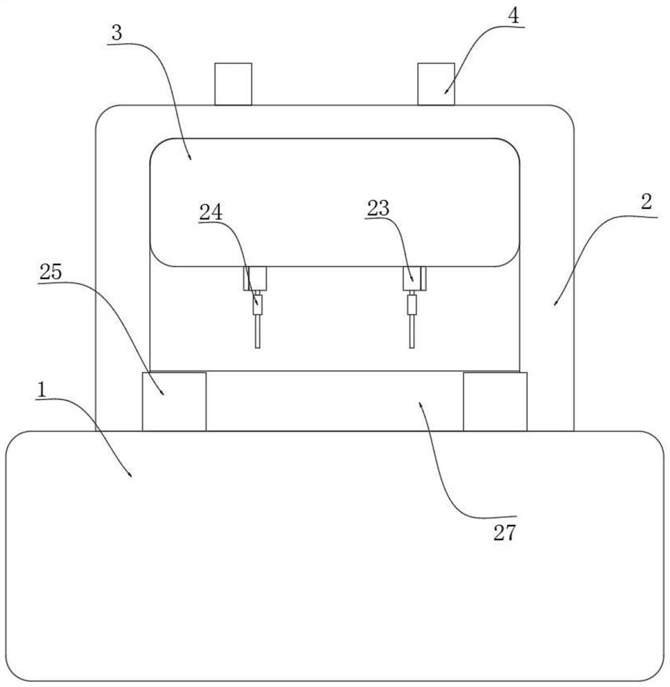
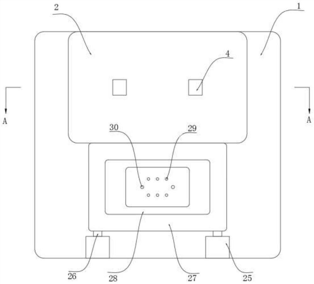
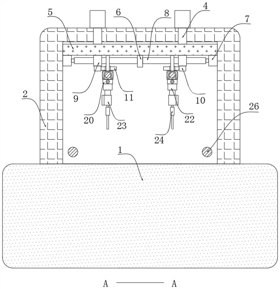
[0033] ReferFigure 1-7 One planar flying needle test device includes a gantry 1 and a machining chamber 2 mounted thereon, and the front end of the processing chamber 2 is fixed having a baffle 3, and two cylinders 4, two cylinders are fixed. The end of the fourth pressure plate 5 is fixed, and the bottom portion of the lower pressure plate 5 is fixed, and both sides of the separator 6 are provided with a positioning mechanism, and the upper end of the gantry 1 is fixed with two upper motors 25, two The output shaft of the upper motor 25 is fixed to the upper wire 26, and the side walls of the two upper filament rods 26 are commonly threaded and connected to the binder 27, and the cartridge 27 is provided with an automatic clamping mechanism.
[0034] The positioning mechanism includes a lateral motor 7 fixed to the bottom of the lower pressure plate 5, and the output shaft of the transverse motor 7 is fixed to the lateral sidewall 8, and the lateral slider 9 is connected to the l...
Embodiment 2
[0044] Refer Figure 8 The difference from the first embodiment is that the buffer mechanism is different, the buffer mechanism includes a separation ring 58 fixed to the inner wall of the buffer 25, and the upper end of the sound ring 58 is opened, and the inner wall sealing of the expansion tank 59 is slid. The top ring 60, the upper end of the top ring 60 fixedly having a plate 56, and the upper end of the plate 56 is co-fixed with the top of the buffer barrel 24, and the bottom portion of the plate 56 is fixed, and the bottom fixing of the link 55 is fixed. There is a probe 48 through the bottom of the buffer cartridge 24, and the internal filling of the expansion tank 59 is filled with a current variable.
[0045] At the time of actual processing, the activation of the cylinder 4 will cause the current soot fluid in the inside of the expansion tank 59 to be electrically powered, and therefore, the current solenoid is expanded and restored, so that the top ring 60 can be pushed...
Embodiment 3
[0047] Refer Figure 9 The difference between the embodiment and the first embodiment is that the angular adjustment mechanism is different, and the angle adjustment mechanism includes the electromagnetic coil 51 and the separator 52 fixed to the inner wall of the propulsion box 41, and the upper end of the separator 52 runs through the sliding bar 54, inserted The sidewalls of the rod 54 are commonly connected to the separator 52, and the inner wall blocking the inner wall of the propulsion box 41 is slidably linked. The upper portion of the propulsion box 41 is filled with a current variable fluid, and the inner wall of the angle box 23 is open. The angle slot 49, both sides of the biased plate 39, respectively, by two equilibrium spring 50, respectively, inner walls of the two angular grooves 49;
[0048] At the time of processing, if the angle of the probe 48 is required, increase the power of the electromagnetic coil 51, control its magnetic field strength size, and control it...
PUM
 Abstract
Description
Claims
Application Information
 - R&D
- Intellectual Property
- Life Sciences
- Materials
- Tech Scout
- Unparalleled Data Quality
- Higher Quality Content
- 60% Fewer Hallucinations
Browse by: Latest US Patents, China's latest patents, Technical Efficacy Thesaurus, Application Domain, Technology Topic, Popular Technical Reports.
© 2025 PatSnap. All rights reserved.Legal|Privacy policy|Modern Slavery Act Transparency Statement|Sitemap|About US| Contact US: help@patsnap.com


