Water-cooling dynamic heat flow sensor

A heat flow sensor and dynamic heat flow technology, applied in calorimeters, instruments, scientific instruments, etc., can solve the problems of low signal-to-noise ratio of thermocouple thermoelectric potential difference signals, cumbersome calibration and measurement of multi-point model heat flow, and small temperature difference in and out of test water, etc. , to improve the accuracy of heat flow calculation, avoid the design of inlet and outlet channels, and ensure the accuracy of testing

Active Publication Date: 2021-10-26
中国空气动力研究与发展中心超高速空气动力研究所
View PDF10 Cites 2 Cited by
  • Summary
  • Abstract
  • Description
  • Claims
  • Application Information

AI Technical Summary

Problems solved by technology

[0003] The traditional water card used in the current water-cooled dynamic heat flow sensor has some limitations or shortcomings. The internal structure of the test inlet and outlet channels is complicated, the processing and assembly are difficult, and the external dimensions are difficult to miniaturize; The signal-to-noise ratio is low; it also involves testing the stable flow control of water and its precise measurement, which brings a lot of tedious work to the multi-point model heat flow calibration

Method used


Image

  • Water-cooling dynamic heat flow sensor
  • Water-cooling dynamic heat flow sensor
  • Water-cooling dynamic heat flow sensor

Examples


Embodiment 1

[0037] When using the present invention, the high-temperature flow field is tested in combination with a hybrid dynamic heat flow test method containing calibration correction:

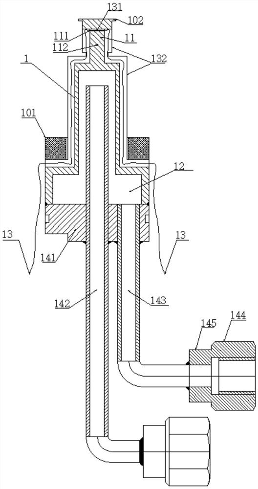
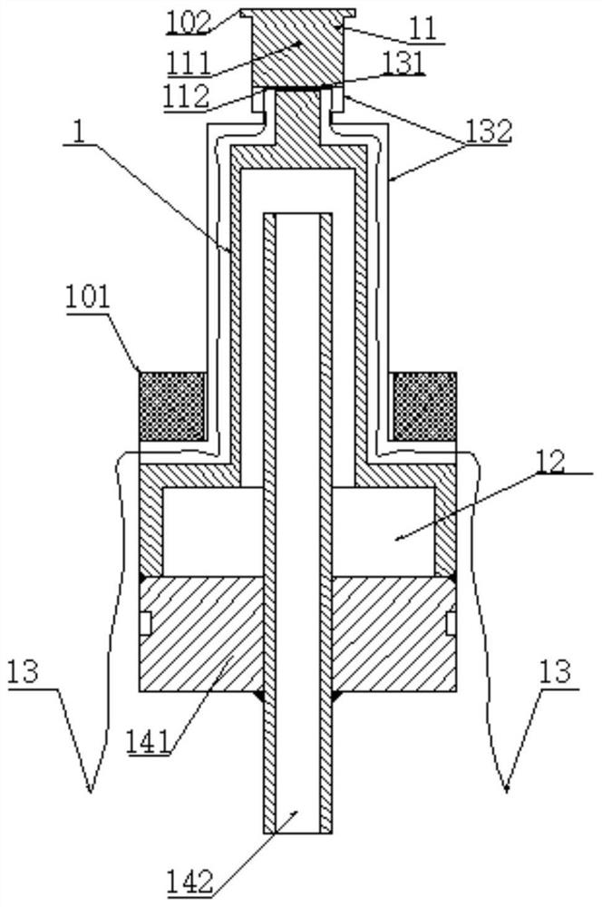
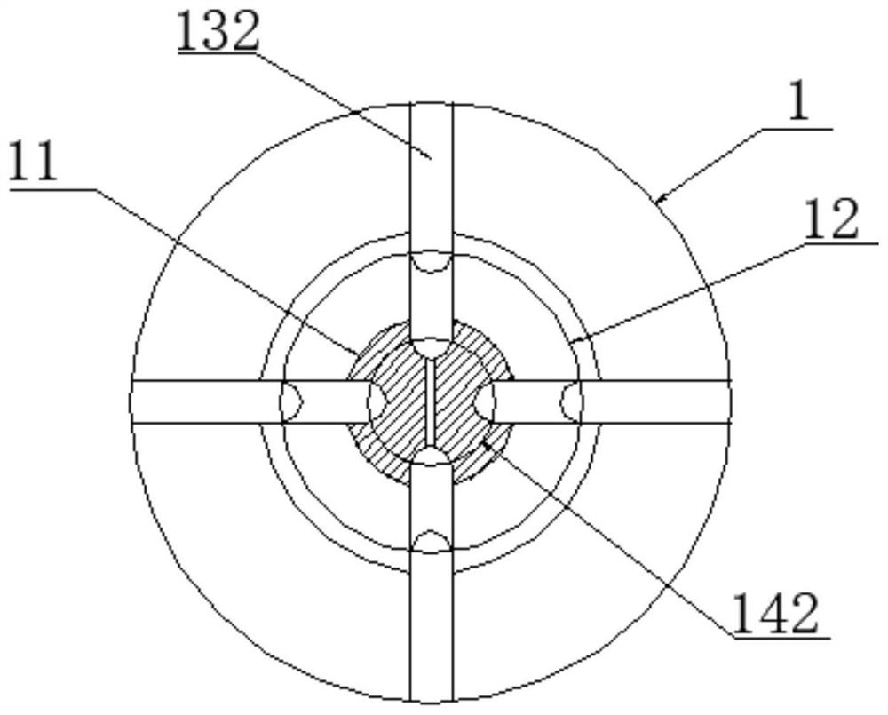
[0038] Step 1. Test the temperature data signal at the center of the two radial through holes on the heat transfer probe 11 of the heat flow sensor body 1 through two butt-type thermocouple wires 12. 1 (k),T 2 (k), the sampling time interval is Δt;

[0039] Step 2: The position from the radial through hole II 112 to the front end of the heat transfer probe 11 is the heat transfer control body; on this basis, according to the principle of energy conservation, combined with heat capacity absorption and one-dimensional heat conduction, an improved hybrid Heat flow test method, the calculation formula is as follows:

[0040]

[0041] Among them, ρ, C, K are respectively the density of the heat flow sensor body 1 (kg / m 3 ), specific heat (J / kg K) and thermal conductivity (W / m K); ΔT 1 (k)=T 1 (k)-T...


PUM

PropertyMeasurementUnit
lengthaaaaaaaaaa
diameteraaaaaaaaaa
thicknessaaaaaaaaaa

Abstract

The invention discloses a water-cooling dynamic heat flow sensor. The sensor comprises a heat flow sensor body which comprises a heat transfer probe and a T-shaped cavity which are coaxially and integrally arranged, two butt-joint thermocouple wires which are arranged on the heat transfer probe in a penetrating manner, and a water cooling device arranged at the lower end of the T-shaped cavity. The heat flow sensor is novel in structure, stable in operation and low in preparation process difficulty, simplifies the design of a test water inlet and outlet channel, and facilitates the miniaturization design of the heat flow sensor; and under the water cooling effect of the T-shaped cavity, the axial temperature gradient of the whole heat flow sensor body is obviously increased, the axial temperature difference signal-to-noise ratio is improved, and the subsequent heat flow calculation precision can be improved. A water cooling device with high cooling efficiency is adopted at the tail part of the T-shaped cavity so that a high-heat-flow long-time test can be realized; and in combination with a hybrid dynamic heat flow test method containing calibration correction, the test accuracy of the designed water-cooling dynamic heat flow sensor is ensured, the heat flow test response speed is improved, and a foundation is laid for a dynamic high heat flow long-time test.

Description

technical field [0001] The invention belongs to the technical field of hypersonic vehicle ground heat protection tests, and in particular relates to a water-cooled dynamic heat flow sensor based on hybrid calorimetry. Background technique [0002] In the aerodynamic heat and heat protection test, the arc wind tunnel and the free jet arc heater test equipment are important ground simulation test equipment for the ground assessment and evaluation of the heat protection material and heat protection structure of hypersonic aircraft. Among them, for the continuous variable parameter test state debugging, the heat flow parameter often adopts the water card steady state heat flow test method that can be tested for a long time. [0003] The traditional water card used in the current water-cooled dynamic heat flow sensor has some limitations or shortcomings. The internal structure of the test inlet and outlet channels is complicated, the processing and assembly are difficult, and the...

Claims


Application Information

Patent Timeline
Patent Type & Authority Applications(China)
IPC IPC(8): G01K17/08
CPCG01K17/08
Inventor 王辉吴东白小娟朱新新杨凯朱涛
Owner 中国空气动力研究与发展中心超高速空气动力研究所
Why Eureka
Try Eureka