Resonance circuit based on chip

A resonant circuit and chip technology, applied in the field of resonant tuning, can solve the problems of improving the resonant soft switching topology loss, reducing the system transmission performance, and increasing the soft switching stress, so as to reduce the topology loss, improve the transmission performance, and improve the detection. The effect of precision

Active Publication Date: 2021-10-29
山东汉芯科技有限公司
View PDF5 Cites 0 Cited by
  • Summary
  • Abstract
  • Description
  • Claims
  • Application Information

AI Technical Summary

Problems solved by technology

[0002] For a passive one-port network including capacitance, inductance, and resistance elements, its ports may exhibit capacitive, inductive, and resistive properties. When the voltage U and current I at the circuit port appear in the same phase and the circuit is resistive, it is called Resonance phenomenon, such a circuit is called a resonant circuit. In the field of wireless transmission supply, the traditional resonant circuit is controlled by simple LLC resonant converter for frequency modulation. When the electric energy output by the resonant circuit is transmitted wirelessly and the distance changes, The resonant frequency will drift, so that the system cannot be maintained in the resonant state, resulting in a decrease in the transmission performance of the system, and it cannot be intelligently tuned according to the chip, resulting in a phase difference between the voltage and current at the output end of the resonant network, thereby improving the resonant soft switching topology. loss, soft switching stress increases

Method used


Image

  • Resonance circuit based on chip
  • Resonance circuit based on chip
  • Resonance circuit based on chip

Examples


Embodiment 1

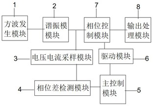
[0020] Embodiment 1: see figure 1 , the embodiment of the present invention provides a chip-based resonant circuit, the chip-based resonant circuit includes: a square wave generating module 1, a resonant module 2, a voltage and current sampling module 3, a phase difference detection module 4, a main control module 5, a drive Module 6, phase control module 7, output processing module 8;

[0021] Specifically, the square wave generating module 1 is used to output a square wave signal according to the input voltage and the drive of the switching tube;

[0022] A resonant module 2, the input end of the resonant module 2 is connected to the output end of the square wave generating module 1, and is used to receive the square wave signal output by the square wave generating module 1 and generate a divided voltage signal and output electric energy;

[0023] A voltage and current sampling module 3, the input end of the voltage and current sampling module 3 is connected to the first ou...

Embodiment 2

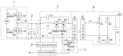
[0030] Embodiment 2: On the basis of Embodiment 1, please refer to figure 2 , in a specific embodiment of the chip-based resonant circuit of the present invention, the square wave generating module 1 includes a power supply DC, a first switching tube M1, a second switching tube M2, a fifth capacitor C5 and a sixth Capacitor C6; the main control module 5 includes a first controller U1;

[0031] Specifically, the first end of the power supply DC is connected to the drain of the first switch M1 and the first end of the fifth capacitor C5, and the second end of the power supply DC is connected to the source of the second switch M2 and the sixth capacitor C6 The first end of the first switch M1, the drain of the first switch M1 is connected to the second end of the sixth capacitor C6, the second end of the fifth capacitor C5 and the source of the first switch M1, the gate of the first switch M1 and The gate of the second switching transistor M2 is connected to the first driving t...

Embodiment 3

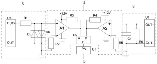
[0039] Embodiment 3: On the basis of Embodiment 2, please refer to image 3 , in a specific embodiment of the chip-based resonant circuit of the present invention, the voltage and current sampling module 3 includes a first resistor R1, a first current transformer U3, a fifth diode D5 and a sixth diode D6;

[0040] Specifically, the first output terminal of the first current transformer U3 is connected to the cathode of the fifth diode D5 and the anode of the sixth diode D6 through the first resistor R1, and the second output terminal of the first current transformer U3, Both the anode of the fifth diode D5 and the cathode of the sixth diode D6 are grounded.

[0041] Further, the voltage and current sampling module 3 also includes a second current transformer U4, a sixth resistor R6 and a fourth capacitor C4;

[0042] Specifically, the first output end of the second current transformer U4 is connected to the first end of the sixth resistor R6 and the first end of the fourth c...


PUM


Abstract

The invention discloses a resonance circuit based on a chip and relates to the technical field of resonance tuning. The resonance circuit comprises a square wave generation module, a resonance module, a voltage and current sampling module, a phase difference detection module, a main control module, a driving module, a phase control module and an output processing module; the square wave generation module is used for generating square wave signals; the resonance module is used for generating voltage division signals; the voltage and current sampling module is used for sampling voltage and current signals; the phase difference detection module is used for detecting voltage and current phase differences; the main control module is used for receiving processing signals and outputting driving signals; the driving module is used for outputting the driving signals; and the phase control module is used for controlling phase shift. According to the resonant circuit based on the chip, a microcontroller is adopted to control a full-control device to realize phase shift control of inductive current, so that dynamic real-time tuning control is performed on the resonant circuit; and a Hall current sensor, an operational amplifier and a logic chip are further utilized to improve the voltage and current phase difference detection precision.

Description

technical field [0001] The invention relates to the technical field of resonance tuning, in particular to a chip-based resonance circuit. Background technique [0002] For a passive one-port network including capacitance, inductance, and resistance elements, its ports may exhibit capacitive, inductive, and resistive properties. When the voltage U and current I at the circuit port appear in the same phase and the circuit is resistive, it is called Resonance phenomenon, such a circuit is called a resonant circuit. In the field of wireless transmission supply, the traditional resonant circuit is controlled by simple LLC resonant converter for frequency modulation. When the electric energy output by the resonant circuit is transmitted wirelessly and the distance changes, The resonant frequency will drift, so that the system cannot be maintained in the resonant state, resulting in a decrease in the transmission performance of the system, and it cannot be intelligently tuned accor...

Claims


Application Information

Patent Timeline
Patent Type & Authority Applications(China)
IPC IPC(8): H02J50/12H03J7/04H02M3/335H02M1/088
CPCH02J50/12H03J7/04H02M3/33569H02M1/083H02M1/088Y02B70/10
Inventor 张航徐辉张孝忠黄子明许虎郭伦强陆伊城
Owner 山东汉芯科技有限公司
Why Eureka
Try Eureka