Material filling type hollow fiber bragg grating and preparation method thereof

A fiber grating, filled-type technology, applied in the directions of cladding fiber, optical waveguide light guide, light guide, etc., can solve the problems of complicated manufacturing process, unfavorable large-area promotion, reduced mechanical strength and service life of optical fiber, etc. Simple, low insertion loss effect

Pending Publication Date: 2021-11-05
HARBIN ENG UNIV
View PDF9 Cites 0 Cited by
  • Summary
  • Abstract
  • Description
  • Claims
  • Application Information

AI Technical Summary

Problems solved by technology

Because this method destroys the fiber core, the mechanical strength and service life of the fiber are

Method used


Image

  • Material filling type hollow fiber bragg grating and preparation method thereof
  • Material filling type hollow fiber bragg grating and preparation method thereof
  • Material filling type hollow fiber bragg grating and preparation method thereof

Examples


Embodiment 1

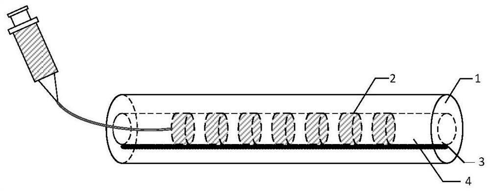
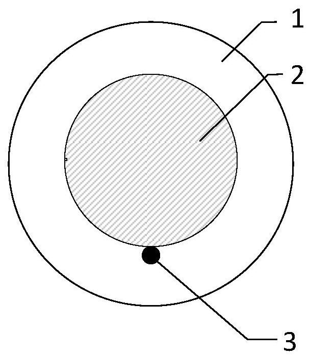
[0032] like figure 1 As shown, a schematic diagram of the preparation of a material-filled hollow fiber grating designed by the present invention includes a four-layer structure: an optical fiber annular cladding, an air hole cladding, an optical fiber grating, and an optical fiber core. Preparation includes the following steps:

[0033] Step 1.1: The capillary is heated and pulled to form a tapered tip with a diameter of about 2 microns. Align the capillary filled with the liquid functional material with the air hole cladding of the capillary fiber to be written, and pressurize the syringe to fill the central air hole of the capillary fiber with the liquid functional material;

[0034] Step 1.2: melt and taper one end of the capillary fiber to be written, and prepare a semi-closed cavity at one end of the fiber;

[0035] Step 1.3: Fix the semi-closed cavity prepared in the previous step in the optical fiber fusion splicer, and then fix the syringe on the syringe pump. By ad...

Embodiment 2

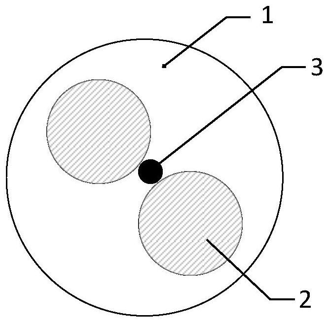
[0038] As shown in Figure 2(b), a schematic diagram of the preparation of a double-hole material-filled hollow fiber grating designed by the present invention, the air holes are symmetrically distributed on both sides of the fiber core, and each air hole is responsible for a grating array. The specific preparation scheme is as follows :

[0039] Step 2.1: The capillary is heated and pulled to form a tapered tip with a diameter of about 2 microns. Align the capillary filled with the liquid functional material with the air hole cladding of the capillary fiber to be written, and pressurize the syringe to make the liquid functional material fill the central air hole (4) of the capillary fiber

[0040] Step 2.2: melt and taper one end of the capillary fiber to be written, and prepare a semi-closed cavity at one end of the fiber;

[0041] Step 2.3: Fix the semi-closed cavity prepared in the previous step in the optical fiber fusion splicer, and then fix the syringe on the syringe p...


PUM


Abstract

The invention provides a material filling type hollow fiber bragg grating and a preparation method thereof. The capillary fiber bragg grating comprises an optical fiber annular cladding, an air hole cladding and an optical fiber core; the distance between the air hole cladding and the optical fiber core is less than 3 micrometers or the air hole cladding is in direct contact with the optical fiber core. The preparation method of the fiber bragg grating comprises the following steps that: the air hole cladding of the fiber is filled with a functional material in a pressurized injection mode; the air hole cladding is periodically filled with the functional material by adjusting the propelling speed, the propelling times and the interval time of an injection pump, so that a refractive index is periodically changed; and finally, fused biconical taper is performed on the capillary optical fiber, and a microfluid channel is blocked, so that the long-period grating array of the air hole cladding of the capillary optical fiber is realized. The material-filled hollow fiber grating designed in the invention has the advantages of low insertion loss, no physical damage to the fiber core, simple structure and the like, realizes reflection of light waves with different wavelengths, and can be applied to multiple fields of optical fiber sensing, biomedical treatment and the like.

Description

technical field [0001] The invention belongs to the technical field of fiber gratings, in particular to a material-filled hollow fiber grating and a preparation method thereof. Background technique [0002] In recent years, the rapid development of fiber gratings has attracted the attention of scientists. The principle of fiber grating is to use the photosensitivity of optical materials to periodically modulate the refractive index of the fiber to form a one-dimensional periodic structure. On the premise of satisfying the phase matching, the fiber grating enables the coupling between the resonant wavelength modes to achieve wavelength selection. Fiber Bragg gratings can be classified into two categories according to their period: Fiber Bragg Gratings (FBG) and Long Period Fiber Gratings (LPFG). The period of fiber Bragg grating is usually several hundreds of nanometers. The coupling occurs between the forward and reverse transmission modes in the fiber core. It can reflect...

Claims


Application Information

Patent Timeline
IPC IPC(8): G02B6/02
CPCG02B6/02123
Inventor 田凤军刘光宇姚晨宇韩忠瑞卢艺鹏李立张建中
Owner HARBIN ENG UNIV
Why Eureka
Try Eureka