
High-efficiency packaging method for MWT assembly

A packaging method and high-efficiency technology, applied in electrical components, semiconductor devices, photovoltaic power generation, etc., can solve the problems of high hole alignment accuracy, black stringing in the lamination process, poor spacing between chips, etc., to increase the curing depth, glue Effect of layer thickness reduction, increased current collection pathway

Inactive Publication Date: 2021-11-23
南京日托光伏新能源有限公司
View PDF4 Cites 0 Cited by
  • Summary
  • Abstract
  • Description
  • Claims
  • Application Information

AI Technical Summary

Problems solved by technology

[0003] The isolation layer between the backplane and the conductive core board of the existing MWT component packaging structure is mostly a whole structure, such as EPE or the whole sheet is coated with an insulating adhesive layer, and then the positive and negative poles are connected to the conductive core by punching holes in the insulating layer. The bonding of metal foil adopts laying method, the process is complex, and requires high hole alignment accuracy, difficult on-site operation, and high production cost. Although the glue coating process can save raw material costs, it is prone to black spots in the lamination process. Bad string spacing, obvious power drop, uneven current after hot spot test

Method used

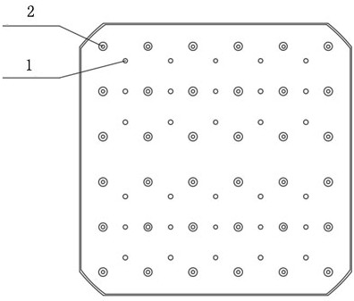
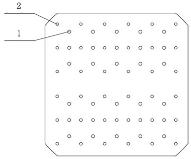
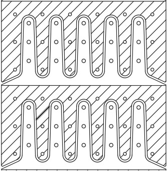

Image

  • High-efficiency packaging method for MWT assembly
  • High-efficiency packaging method for MWT assembly
  • High-efficiency packaging method for MWT assembly

Examples


Embodiment 1

[0040] Polyurethane thickness 25mm, oven temperature 80°C, oven time 2min, epoxy acrylic thickness 5mm, UV exposure time 30s, total thickness of adhesive layer 30mm, lamination temperature 138°C for one chamber, lamination time for one chamber 7min, two chambers The pressing temperature is 142°C, and the lamination time for one cavity is 7 minutes.

Embodiment 2

[0042] Polyurethane thickness 20mm, oven temperature 80°C, oven time 1min, epoxy acrylic thickness 10mm, UV light time 35s, total thickness of adhesive layer 30mm, lamination temperature 138°C for one cavity, lamination time for one cavity 7min, two-cavity layer The pressing temperature is 142°C, and the lamination time for one cavity is 7 minutes.

Embodiment 3

[0044] Polyurethane thickness 20mm, oven temperature 80°C, oven time 1min, epoxy acrylic thickness 15mm, UV exposure time 40s, total thickness of adhesive layer 30mm, lamination temperature 138°C for one chamber, lamination time for one chamber 7min, two chambers The pressing temperature is 142°C, and the lamination time for one cavity is 7 minutes.


PUM

PropertyMeasurementUnit
thicknessaaaaaaaaaa
thicknessaaaaaaaaaa
thicknessaaaaaaaaaa

Abstract

The invention provides a high-efficiency packaging method for an MWT assembly, which comprises the following steps of firstly coating polyurethane resin on a conductive metal foil, and performing solvent volatilization and primary curing after passing through a drying tunnel, then spraying epoxy acrylic resin on the surface layer of the polyurethane resin, and curing the epoxy acrylic resin on the surface layer through ultraviolet irradiation, after laser drilling is carried out on the insulating layer, conducting battery piece placement, and finally, laying other materials for producing the assembly, and carrying out secondary lamination curing in a laminating machine. The packaging surface obtained through the method has certain strength and hardness, uneven current caused by layering due to insufficient bonding strength in the long-term outdoor use process is avoided, the lamination subfissure proportion and the glue hole blocking proportion in the lamination process are improved, the lamination time rhythm can be adjusted, the power is improved, and hot spots are improved.

Description

technical field [0001] The invention relates to the field of photovoltaic components, in particular to an efficient packaging method for MWT components. Background technique [0002] In conventional MWT photovoltaic modules, since the positive and negative poles of the component cells are arranged on the back of the battery sheet, conductive glue is usually used to bond the electrode points to the conductive core plate, and the positive and negative pole currents are collected by the conductive core plate, because the positive and negative electrodes are on the back of the battery. On the back side, when packaging, a special insulating material film must be laid on the battery sheet and the conductive core board to separate the battery sheet from the conductive metal foil. At present, the packaging structure of MWT components from top to bottom is glass, EVA, battery sheet, and insulating material. Layer, metal conductive circuit layer, encapsulation film layer, backplane la...

Claims


Application Information

Patent Timeline
Patent Type & Authority Applications(China)
IPC IPC(8): H01L31/18H01L31/048
CPCH01L31/18H01L31/048H01L31/0481Y02E10/50
Inventor 孙影逯好峰吴仕梁张凤鸣梁东海
Owner 南京日托光伏新能源有限公司
Learn More