Vacuum adsorption clamp and adsorption method for clamping thin-wall spherical shell type micro component

A technology of vacuum adsorption and vacuum suction head, which is applied in the direction of clamping, positioning devices, clamping devices, etc., can solve the problems of low repeat positioning accuracy, complex control parts, and large deformation of the spherical shell, so as to facilitate the secondary accurate tool setting , Guaranteed processing accuracy and small deformation effect

Active Publication Date: 2021-11-26
HARBIN INST OF TECH
View PDF11 Cites 1 Cited by
  • Summary
  • Abstract
  • Description
  • Claims
  • Application Information

AI Technical Summary

Problems solved by technology

[0006] The technical problem to be solved by the present invention is: in the process of processing the thin-walled spherical micro-components uniformly distributed on the entire surface of the micro-pit structure, the existing clamping method is difficult to operate and the control parts are relatively complicated, resulting in large deformation of the spherical shell and repetitive In order to solve the problems of low positioning accuracy, and then provide a vacuum adsorption fixture and adsorption method for the clamping of small components of thin-walled spherical shells

Method used


Image

  • Vacuum adsorption clamp and adsorption method for clamping thin-wall spherical shell type micro component
  • Vacuum adsorption clamp and adsorption method for clamping thin-wall spherical shell type micro component
  • Vacuum adsorption clamp and adsorption method for clamping thin-wall spherical shell type micro component

Examples


Embodiment Construction

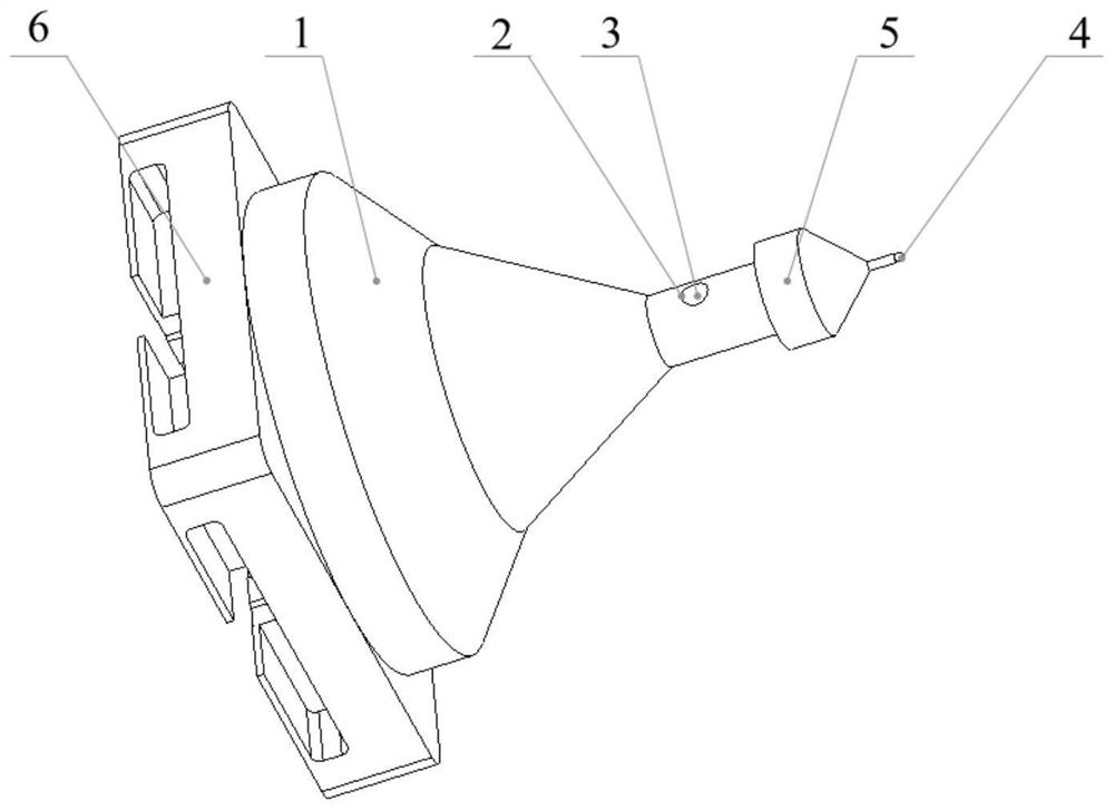
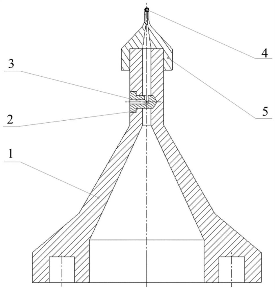
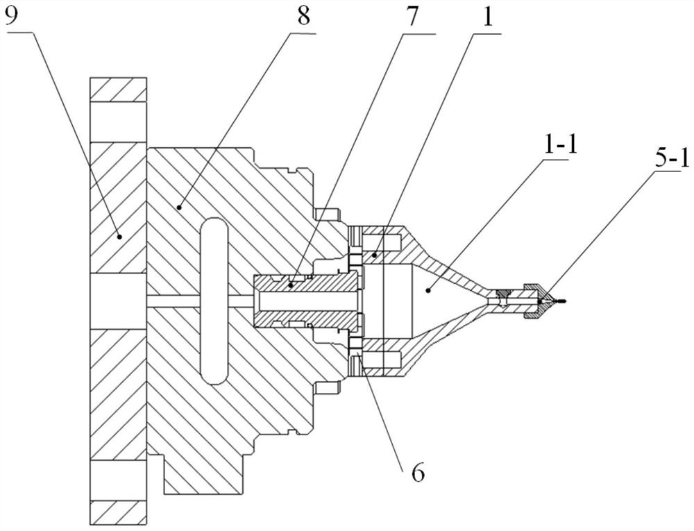
[0057] combined with Figure 1-9 , the realization of the present invention is described as follows:

[0058] Such as Figure 1-6 As shown, the vacuum adsorption fixture used for clamping thin-walled spherical shell micro components according to the present invention includes a vacuum adsorption fixture main body 1 and a vacuum suction head 5. 5 is sealed and detachably connected to the adsorption end of the vacuum adsorption fixture main body 1, the connection end of the vacuum adsorption fixture main body 1 is used to connect with the reference piece of the zero point positioning quick change device, and the end of the vacuum suction head 5 is used to absorb the tiny thin-walled spherical shell 4; The vacuum cavity 1-1 on the main body of the vacuum adsorption fixture along its axial direction becomes smaller along the connecting end to the adsorption end; the vacuum cavity 1-1 is used as the main air source channel, and the main body of the vacuum adsorption fixture 1 is o...


PUM


Abstract

The invention provides a vacuum adsorption clamp and an adsorption method for clamping a thin-wall spherical shell type micro component, and relates to the technical field of clamping of thin-wall spherical shell type micro components. The vacuum adsorption clamp and the adsorption method are provided for solving the problems that in the machining process of uniformly distributing micro pit structures on the whole surface of the thin-wall spherical shell type micro component, an existing clamping mode is difficult to operate, a control part is complex, consequently, spherical shell deformation is large, and the repeated positioning precision is low. According to the technical key points, a vacuum suction head is detachably connected with the adsorption end of a vacuum adsorption clamp body in a sealed mode, and the hole diameter of a vacuum cavity in the vacuum adsorption clamp body in the axial direction of the vacuum adsorption clamp body is decreased from the connecting end to the adsorption end; and the vacuum cavity serves as a main air source channel, and an auxiliary air source connector communicating with the vacuum cavity is formed in the vacuum adsorption clamp body. When the vacuum adsorption clamp is adopted to adsorb the thin-wall spherical shell type micro component, the specific structure shape of the suction head and the vacuum negative pressure are calculated and checked. A clamp chuck is suitable for flexibly adjusting the vacuum degree according to the deformation condition of a thin-wall spherical shell, that is, the suction force of the clamp chuck is adjusted, clamping deformation is reduced, and the machining precision is guaranteed.

Description

technical field [0001] The invention relates to a vacuum adsorption fixture and an adsorption method for clamping thin-walled spherical shell micro components, and relates to the technical field of thin-wall spherical shell micro components clamping. [0002] technical background [0003] With the continuous development and progress of science and technology, various thin-walled spherical shell micro components with weak stiffness are widely used in the fields of biomedicine, electronic information, aerospace, national defense and military, etc., and the surface shape is required to reach sub-micron shape accuracy, Nanoscale surface roughness and minimal subsurface damage. It is necessary to adopt appropriate clamping methods to reduce clamping deformation and ensure that the workpiece is not damaged, and ultra-precision micro-milling can achieve high-precision machining of the full-surface cross-scale feature structure. [0004] For example, thin-walled spherical shell micr...

Claims


Application Information

Patent Timeline
Patent Type & Authority Applications(China)
IPC IPC(8): B23Q3/00B23C3/00
CPCB23Q3/00B23C3/00B23Q2703/10B23Q2703/04
Inventor 陈明君郭锐阳李国于天宇王广洲周星颖
Owner HARBIN INST OF TECH
Why Eureka
Try Eureka