Carbonization device

A gas furnace and dryer technology, which is applied in special forms of dry distillation, petroleum industry, biofuels, etc., can solve the problems of lower combustion value, lower quality of carbon products, and low carbon production efficiency, and achieves improved heat transfer efficiency and raw materials. The effect of cost reduction and labor cost reduction

Pending Publication Date: 2021-12-07
FOSHAN HUAJIEYUAN THERMAL ENERGY & ENVIRONMENTAL ENG TECH CO
View PDF0 Cites 0 Cited by
  • Summary
  • Abstract
  • Description
  • Claims
  • Application Information

AI Technical Summary

Problems solved by technology

[0010] If the above method 1 is adopted, heating by heat radiation or heat conduction will cause the material to be heated very slowly, resulting in low carbon production efficiency and large heat loss.
When straw with a loose structure is used as raw material, because there is a large amount of air in the straw, the air will cause the combustion of the straw and produce a large amount of ash in a high-temperature environment. This is different from the situation of making charcoal from large pieces of wood. It is difficult to separate when mixed with loose straw carbonized materials, resulting in a decrease in the grade of charcoal products
If the heat is supplied by burning wood externally, the smoke produced will cause environmental pollution
[0011] If the above-mentioned method 2 is adopted, the ash content of the straw burnt and the charcoal material will also be mixed by heating with the high-temperature flue gas generated by burning part of the straw. Unlike wood charcoal, the volume of wood charcoal after charcoal does not change much. It is easy to separate from the ash, and the straw will become thin and brittle small fragments or powder after carbonization, which is difficult to separate after being mixed with the ash, resulting in a decrease in the calorific value per unit mass of the carbon product, reducing the grade and value of the carbon product
This method burns part of the straw, resulting in a lower charcoal yield, and the gas emitted by dry distillation causes air pollution
[0012] If the above method 3 is adopted, heating by introducing high-temperature flue gas generated by burning waste wood externally will cause serious pollution to the environment due to the discharge of pyrolysis gas. Mixing a large amount of carbon dioxide gas reduces its combustion value, and the pyrolysis gas with low combustion value is difficult to burn directly or the flue gas produced by combustion cannot reach the flue gas temperature required for pyrolysis
This method also has the problem that the oxygen contained in the straw will cause combustion when it is pyrolyzed again, and the generated ash will be mixed into the carbonized material.

Method used


Image

  • Carbonization device
  • Carbonization device
  • Carbonization device

Examples


Embodiment 1

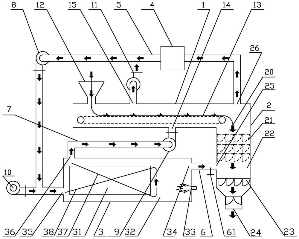
[0037] Embodiment 1: A kind of charcoal making device, comprises drier 1, pyrolysis furnace 2 and gas furnace 3; Described drier 1 is provided with feed inlet 12, low-temperature flue gas inlet 14 and tail gas outlet 15, so The dryer 1 described above is provided with a material conveying mechanism 13 inside; the top position of the pyrolysis furnace 2 is provided with a pyrolysis gas outlet 26, its upper position is provided with a material inlet 20, and its middle position is provided with a high-temperature smoke outlet. The gas receiving room 22 is provided with a discharge port 24 at its lower position; the pyrolysis furnace 2 is provided with a multi-layer breathable material down transmission mechanism 21 between the material inlet 20 and the high-temperature flue gas receiving room 22; A shutter 23 is provided between the high-temperature flue gas receiving room 22 and the discharge port 24; the gas furnace 3 is composed of a gas furnace heat exchanger 31 and a gas furn...

Embodiment 2

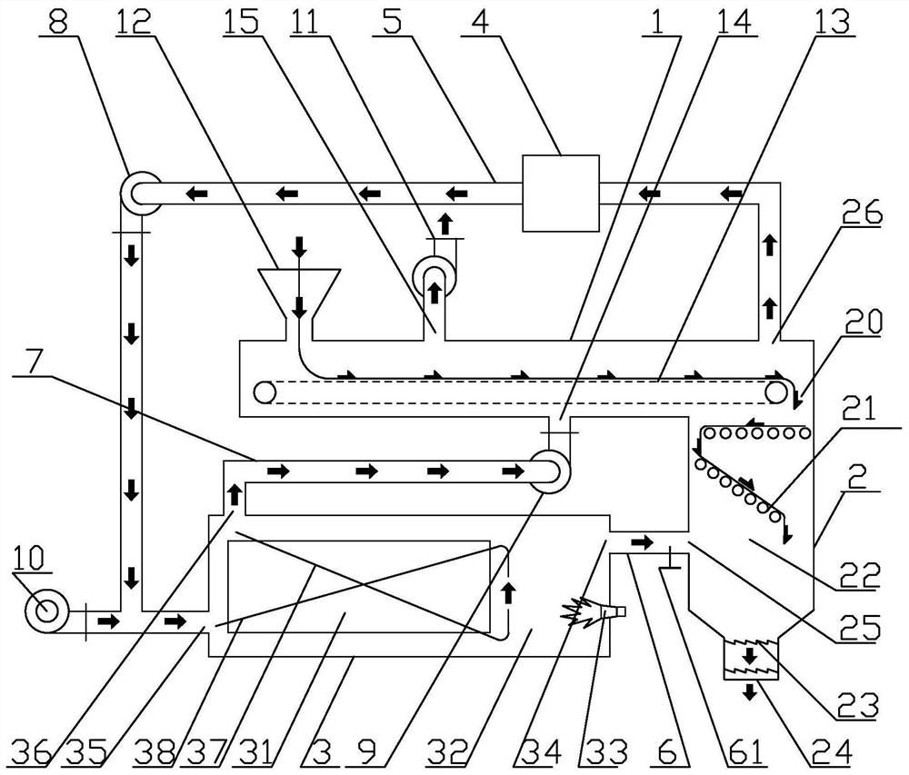
[0054] Embodiment 2: as figure 2 As shown, a charcoal making device includes a dryer 1, a pyrolysis furnace 2 and a gas furnace 3; the dryer 1 is provided with a feed inlet 12, a low-temperature flue gas inlet 14 and an exhaust gas outlet 15, and the The drying machine 1 is provided with a material conveying mechanism 13 inside; the top position of the pyrolysis furnace 2 is provided with a pyrolysis gas outlet 26, the upper position is provided with a material inlet 20, and the middle position is provided with a high-temperature flue gas The receiving room 22 is provided with a material outlet 24 at its lower position; the pyrolysis furnace 2 is provided with a multi-layer breathable material down-passing mechanism 21 between the material inlet 20 and the high-temperature flue gas receiving room 22; A shutter 23 is provided between the high-temperature flue gas receiving room 22 and the discharge port 24; the gas furnace 3 is composed of a gas furnace heat exchanger 31 and a...

Embodiment 3

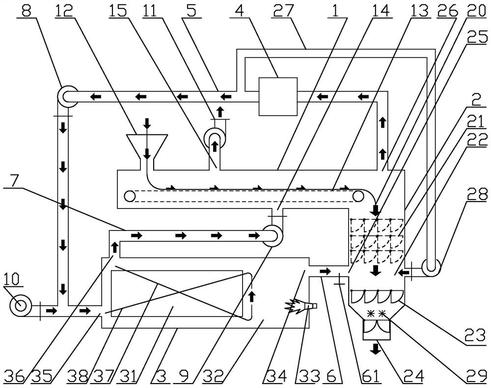
[0064] Embodiment 3: as image 3 , a charcoal production device, including a dryer 1, a pyrolysis furnace 2 and a gas furnace 3; Dryer 1 is provided with a material conveying mechanism 13 inside; the top position of the pyrolysis furnace 2 is provided with a pyrolysis gas outlet 26, the upper position is provided with a material inlet 20, and the middle position is provided with a high-temperature flue gas receiving room 22, its lower position is provided with a discharge port 24; the pyrolysis furnace 2 is provided with a multi-layer breathable material down transmission mechanism 21 between the feed port 20 and the high-temperature flue gas receiving room 22; the high-temperature A flashboard 23 is provided between the flue gas receiving room 22 and the discharge port 24; the gas furnace 3 is composed of a gas furnace heat exchanger 31 and a gas furnace hearth 32; One end is located in the hearth 32 of the gas furnace; the heat exchanger 31 of the gas furnace is provided wi...


PUM


Abstract

The invention discloses a carbonization device. The carbonization device comprises a drying machine, a pyrolyzing furnace and a gas furnace; the drying machine is provided with a material inlet, a low-temperature flue gas inlet and a tail gas outlet, and a material conveying mechanism is arranged in the drying machine; the dryer is communicated with the interior of the pyrolyzing furnace, and a material conveying mechanism in the dryer extends to a feeding port above the pyrolyzing furnace; a pyrolysis gas outlet of the pyrolysis furnace is communicated to a pyrolysis gas inlet of the gas furnace heat exchanger; the gas furnace heat exchanger is provided with a fan for independently supplying air to the pyrolysis gas inlet of the gas furnace heat exchanger; the hearth of the gas furnace is communicated with the high-temperature flue gas receiving room of the pyrolyzing furnace through a high-temperature flue gas conveying pipe; and a low-temperature flue gas outlet of the gas furnace heat exchanger is communicated to a low-temperature flue gas inlet of the dryer through a pipeline and a fan. The carbonization efficiency is improved by dozens of times; harmful gas and particulate matters in the tail gas are decomposed and filtered respectively; the raw material cost is greatly reduced; and the labor cost is reduced.

Description

technical field [0001] The invention relates to a charcoal making device, in particular to a charcoal making device suitable for light and loose plants as raw materials, and belongs to the technical fields of energy saving, environmental protection and equipment manufacturing. Background technique [0002] Rural areas will produce a large amount of rice straw, wheat straw, corn stalk and other straws during the harvest season. At present, except for a small part of the huge amount of straw, which is used to make fuel, feed and compost, most of it is not well utilized and is accumulated in large quantities. The straw has become an urgent problem to be solved in the vast rural areas. Many farmers use illegal burning methods to dispose of it, causing serious air pollution and causing frequent wildfires. [0003] The government has been actively promoting the comprehensive utilization of straw, and converting straw into clean energy and fertilizer is the main direction. At pres...

Claims


Application Information

Patent Timeline
Patent Type & Authority Applications(China)
IPC IPC(8): C10B53/02C10B57/10C10B49/02C10B57/18
CPCC10B53/02C10B57/10C10B49/02C10B57/18Y02E50/10
Inventor 林建东徐健元陈永基
Owner FOSHAN HUAJIEYUAN THERMAL ENERGY & ENVIRONMENTAL ENG TECH CO
Why Eureka
Try Eureka