
Design and preparation method of micro-channel structure of efficient enhanced boiling heat transfer surface

A microchannel structure and enhanced boiling technology, applied in the field of phase change heat transfer, can solve the problems that the bubble growth characteristics in the microchannel structure cannot be significantly changed, the surface boiling heat transfer performance cannot be greatly improved, and large-scale commercialization cannot be achieved. , to achieve the effects of reducing thermal expansion coefficient mismatch and heat transfer loss, increasing critical heat flux, and increasing the number of nucleation sites

Pending Publication Date: 2021-12-10
BEIHANG UNIV
View PDF9 Cites 2 Cited by
  • Summary
  • Abstract
  • Description
  • Claims
  • Application Information

AI Technical Summary

Problems solved by technology

In addition, the processing methods to improve the boiling heat transfer performance in the prior art are expensive (such as the template method), cannot be commercialized on a large scale, and cannot significantly change the growth characteristics of the bubbles in the microchannel structure, so that the surface boiling heat transfer cannot be greatly improved. performance

Method used


Image

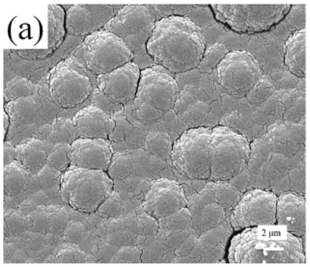
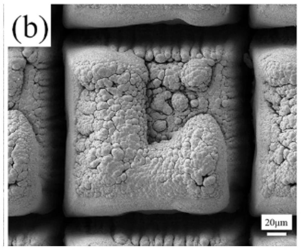
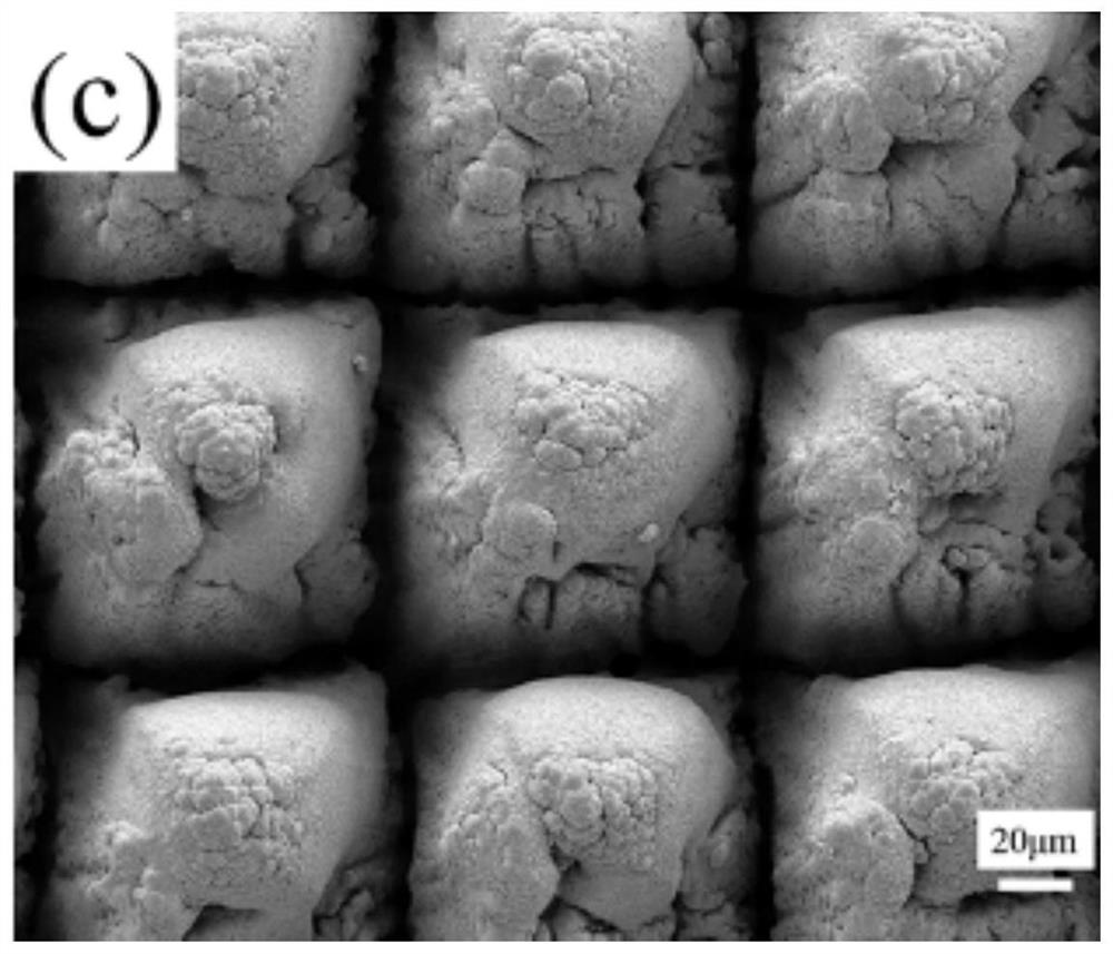
  • Design and preparation method of micro-channel structure of efficient enhanced boiling heat transfer surface
  • Design and preparation method of micro-channel structure of efficient enhanced boiling heat transfer surface
  • Design and preparation method of micro-channel structure of efficient enhanced boiling heat transfer surface

Examples


Embodiment 1

[0036] This embodiment provides a method for designing and preparing a microchannel structure that efficiently enhances the boiling heat transfer surface, including the following steps:

[0037] (1) Take a copper cylinder with a diameter of 10mm and a height of 20mm, and use laser processing to form a microchannel structure on the surface of the copper cylinder;

[0038] The concrete condition of described laser processing is set as:

[0039] Design a "well" shape structure on the laser platform (Wuhan Anyon Laser, model PicoYL-15), the distance between the two nearest laser processing lines is 0.2mm; the laser wavelength is 1064nm, the spot diameter is 50μm, and the total power 15W;

[0040] The cross-section of the microchannel structure is a rectangle, and the width of the rectangle is 0.2mm (corresponding to the interval between two lines of the "well" shape structure), and the channel (groove) width of the microchannel structure is 0.2mm, The depth is 312 μm;

[0041](...

Embodiment 2

[0043] The difference between embodiment 2 and embodiment 1 is only: in step (1), when laser processing is adopted, the interval between the two lines of the "well"-shaped structure is 0.1mm, and others are the same as embodiment 1; correspondingly, this The cross-section of the microchannel structure obtained in the embodiment is rectangular, and the width of the rectangle is 0.1 mm. The channel (groove) of the microchannel structure has a width of 0.1 mm and a depth of 367 μm.

Embodiment 3

[0045] The difference between this embodiment 3 and embodiment 1 is that in step (1), when laser processing is used, the interval between the two lines of the "well"-shaped structure is 0.03 mm, and the others are the same as in embodiment 1. Correspondingly, the cross-section of the microchannel structure obtained in this embodiment is rectangular, the width of the rectangle is 0.03 mm, the channel (groove) width of the microchannel structure is 0.03 mm, and the depth is 256 μm.


PUM

PropertyMeasurementUnit
depthaaaaaaaaaa
diameteraaaaaaaaaa
heightaaaaaaaaaa

Abstract

The invention relates to a design and preparation method of a micro-channel structure of an efficient enhanced boiling heat transfer surface. According to the invention, a micro-channel structure is cut on a high-thermal-conductivity metal copper surface through laser, then a copper nano layer is deposited on the micro-channel structure through a magnetron sputtering method, the superheat temperature of the high-thermal-conductivity metal surface is reduced while the critical heat flux density of the high-thermal-conductivity metal surface is improved, and the critical heat flux density and the heat exchange coefficient are enhanced at the same time. The number of nucleation sites of the micro-channel structure is increased, the critical heat flux density is increased by 1.61 times compared with the surface of a copper material, meanwhile, the heat exchange coefficient is increased by 2.26 times, and the superheat degree of the metal heat exchange surface making contact with liquid is greatly reduced. The surface of the micro-channel structure is provided with the closely-stacked nano-column layer, the bubble removal diameter is smaller, and the bubble removal frequency is higher. According to the efficient enhanced boiling heat transfer surface with the multi-stage micro-channel structure, the critical heat flux is as high as 141.3 W / cm < 2 >, and the superheat degree of the wall surface is only 8.9 K.

Description

[0001] The invention belongs to the technical field of phase change heat transfer, and in particular relates to a microchannel structure design and a preparation method of a highly efficient enhanced boiling heat transfer surface. Background technique [0002] The rapid development of high-tech fields such as integrated circuits, high-performance computers, laser precision machining, and aerospace has led to a continuous increase in the heat flux of electronic components. If such high-intensity heat generation cannot be effectively removed, the temperature of the device will rise rapidly, seriously Reduce device and system performance, stability, and security. The heat dissipation of devices has become a key bottleneck affecting the development of today's electronics industry. Boiling heat transfer is a heat transfer method in which the working fluid takes away the heat from the heating surface through the movement of bubbles and cools it down. It can obtain a large heat trans...

Claims


Application Information

Patent Timeline
Patent Type & Authority Applications(China)
IPC IPC(8): H01L21/48H01L23/367H01L23/373H01L23/427
CPCH01L21/4871H01L23/367H01L23/3736H01L23/427
Inventor 邓元海丰勋祝薇
Owner BEIHANG UNIV
Learn More