
Optical fiber isolator

A fiber optic isolator and isolation module technology, applied in the direction of lasers, laser components, phonon exciters, etc., can solve the problems of complex system structure, low integration, and multiple melting points, so as to reduce production costs, reduce fusion points, The effect of reducing loss

Active Publication Date: 2021-12-10
GAUSS LASERS TECH (SHANGHAI) CO LTD
View PDF13 Cites 1 Cited by
  • Summary
  • Abstract
  • Description
  • Claims
  • Application Information

AI Technical Summary

Problems solved by technology

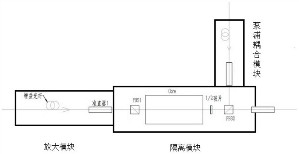
[0006] In view of this, in order to solve the above problems, the present invention provides an optical fiber isolator, through the amplification module, the pump coupling module and the isolation module, the optical fiber isolator integrates the pump reverse coupling, amplification and isolation functions, compared with the existing There are technologies that reduce the use of optical fiber combiners and passive optical fibers, thereby achieving the beneficial effects of reducing fusion points, reducing losses, and improving system integration and stability, thereby solving the problems of many optical fiber components and multiple melting points in the prior art. , high loss, complex system structure and low integration

Method used


Image

  • Optical fiber isolator
  • Optical fiber isolator
  • Optical fiber isolator

Examples


Embodiment 1

[0040] Such as figure 2 As shown, the fiber isolator in this embodiment includes an amplification module, a pump coupling module and an isolation module; the amplification module includes a gain fiber and a collimator 1 connected in sequence; the pump coupling module includes a passive fiber 1 connected in sequence and the second collimator; the isolation module includes the first polarization beamsplitter prism (PBS1), Faraday rotator (Core), 1 / 2 glass slide, the second polarization beamsplitter prism (PBS2), the third collimator and Passive optical fiber 2; wherein, the pump coupling module is arranged at the rear end of the isolation module, which is suitable for polarization-maintaining fiber core pump amplification mode, and plays the role of pump reverse coupling, amplification and isolation.

Embodiment 2

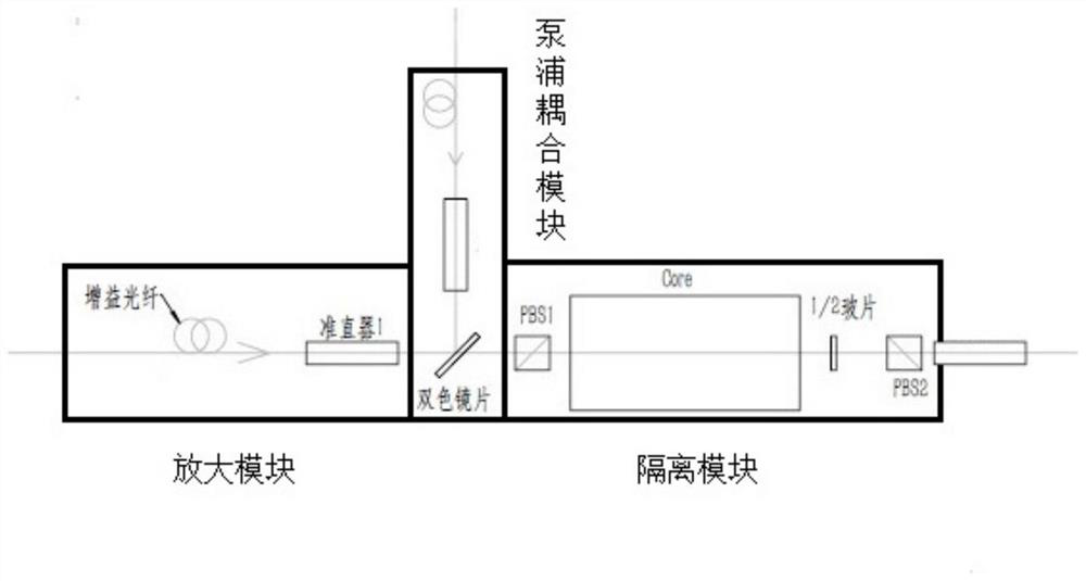
[0042] Such as image 3 As shown, the difference from Embodiment 1 is that the pump coupling module in the fiber isolator in this embodiment is arranged at the front end of the isolation module, which is suitable for core pumping and cladding pumping, and the pumping light does not pass through the Faraday optical rotator.

Embodiment 3

[0044] Such as Figure 4 As shown, on the basis of Embodiment 1, further, the output mode of the optical fiber isolator in this embodiment is optical fiber output, that is, an online optical fiber isolator, which is generally used in the middle of a fiber laser system to serve as a coupling pump , amplification, and isolation; its structure includes: gain fiber, collimator 1 (the first collimator), PBS1 (the first polarization beam splitter), Core (Faraday rotator), 1 / 2 slide, PBS2 ( second polarization beam splitter), collimator 2 (second collimator); wherein, gain fiber, collimator 1, PBS1, Faraday rotator, 1 / 2 slide, PBS2, collimator 3 and passive The optical fiber 2 is connected sequentially; the passive optical fiber 1 is directly connected to the input end of the collimator 2, and the output end of the collimator 2 is connected to the PBS2. After being collimated by the collimator 3, the amplified signal light passes through the wireless Source fiber 2 output. The firs...


PUM


Abstract

The invention relates to an optical fiber isolator, which comprises an amplification module, a pumping coupling module and an isolation module, wherein the amplification module comprises a gain optical fiber and a first collimator, the pumping coupling module comprises a first passive optical fiber and a second collimator, and the isolation module comprises a first polarization splitting prism, a Faraday rotator, a 1 / 2 slide, a second polarization splitting prism, a third collimator and a second passive optical fiber. According to the invention, signal light passes through the gain optical fiber and is amplified under pumping excitation, and the amplified light passes through the isolation module; the optical fiber isolator integrates pumping reverse coupling, amplification and isolation functions, the use of passive optical fibers of an optical fiber beam combiner is reduced, welding points are reduced, the loss is small, and the integration level and the stability of the system are improved; and the length of a pulse laser transmission optical fiber is reduced, the nonlinear effect is reduced, and the amplification characteristic and the amplification structure of the pulse optical fiber laser are optimized.

Description

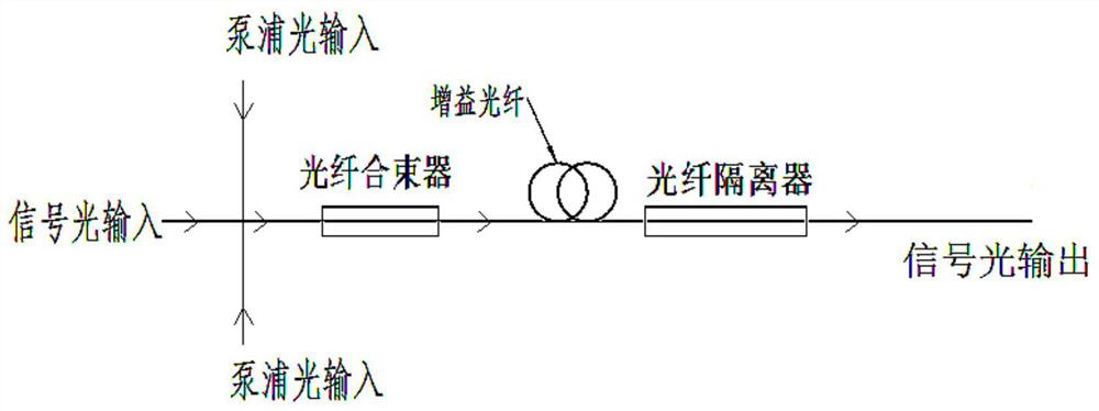
technical field [0001] The invention belongs to the field of laser devices, in particular to an optical fiber isolator. Background technique [0002] In the fiber laser oscillation or amplification system, in order to prevent the amplified energy from being reflected back, causing damage to the previous-stage devices or forming self-excited oscillations, fiber optic isolators are generally used for optical isolation protection to prevent the latter-stage energy from being reflected back to the previous stage. [0003] See figure 1 , in the current fiber laser and amplification system, a fiber combiner (cladding pump) or a wavelength division multiplexer (core pump) is generally used to couple the pump light into the gain fiber for amplification, and then isolate it through the fiber device for isolation protection. However, whether it is a beam combiner or a wavelength division multiplexer as a passive optical coupling device, it is inevitable to introduce various losses d...

Claims


Application Information

Patent Timeline
Patent Type & Authority Applications(China)
IPC IPC(8): H01S3/067H01S3/094
CPCH01S3/06754H01S3/094003
Inventor 任红艳吴明周士云冷雨欣刘志文刘家顺蔡一鸣周士安
Owner GAUSS LASERS TECH (SHANGHAI) CO LTD
Learn More