Multi-cavity heat insulation flow guide pipe with heat insulation structure and preparation method thereof

A diversion tube and heat insulation technology, which is applied in heat exchange equipment, lighting and heating equipment, and pipeline protection through heat insulation, can solve the problems of large engineering volume, low utilization rate, and low temperature of soil heat energy, and achieve the goal of occupying an area The effect of small area and high utilization efficiency

Inactive Publication Date: 2021-12-14
北京千城集成房屋有限公司
View PDF6 Cites 1 Cited by
  • Summary
  • Abstract
  • Description
  • Claims
  • Application Information

AI Technical Summary

Problems solved by technology

[0003] The existing conventional geothermal energy utilization has the following disadvantages: 1. Utilization of water that exists on the surface of the earth’s crust and is exposed to the atmosphere, such as river water, river water, lake water, reservoir water, etc., has relatively large constraints on the location of utilization; extract hot water and discharge it into cold water It will cause the temperature of the local water body to rise or fall, which will affect the distribution of the temperature field of the water body in a specific area, and then cause certain pollution to the water environment.
The temperature of the hydrothermal resources existing on the surface is relatively low, and the traditional diversion pipe has a large heat loss, so the heat utilization value of the surface water source system is low, and other energy sources are needed to assist the work
2. The heat energy temperature of the shallow soil is low, so in order to provide a certain amount of heat energy, a large area of ​​pipelines needs to be buried; the soil source heat pump occupies a large area, the amount of engineering is large, the investment is large and the benefit is low; the heating process will lead to regional thermal imbalance; The shallow soil temperature is relatively low, and t

Method used


Image

  • Multi-cavity heat insulation flow guide pipe with heat insulation structure and preparation method thereof
  • Multi-cavity heat insulation flow guide pipe with heat insulation structure and preparation method thereof
  • Multi-cavity heat insulation flow guide pipe with heat insulation structure and preparation method thereof

Examples


Embodiment 1

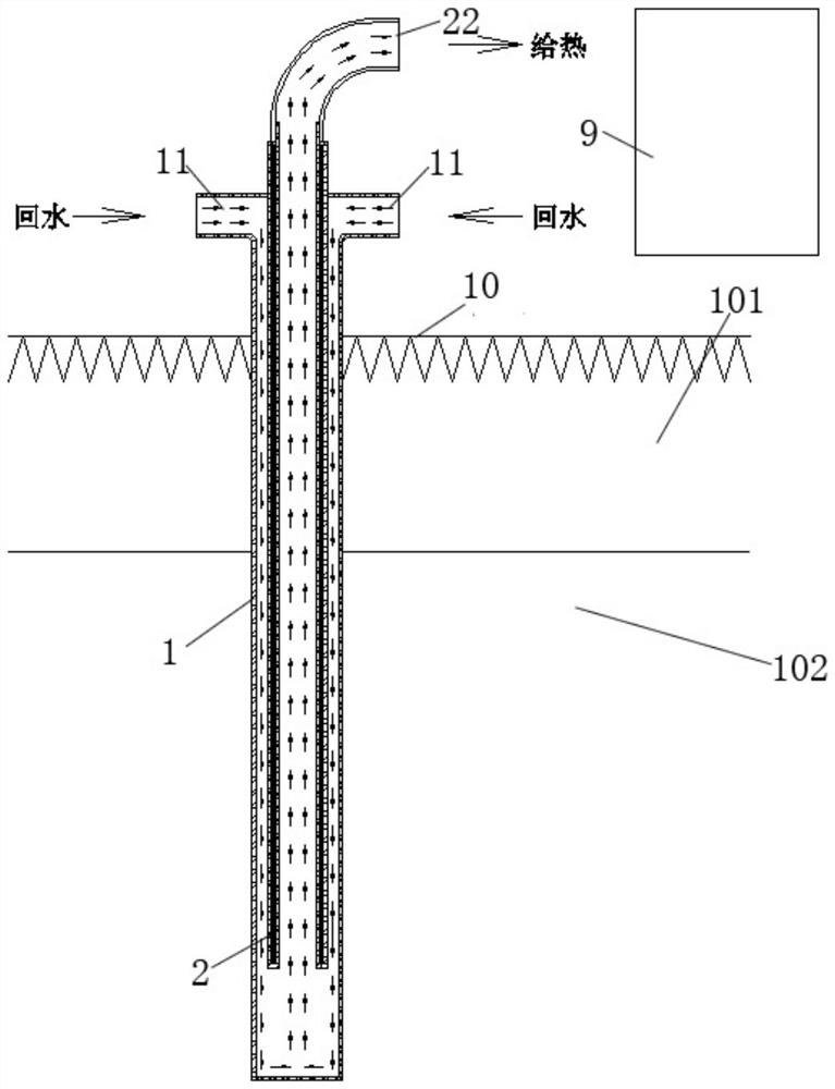
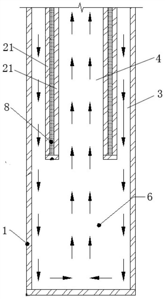
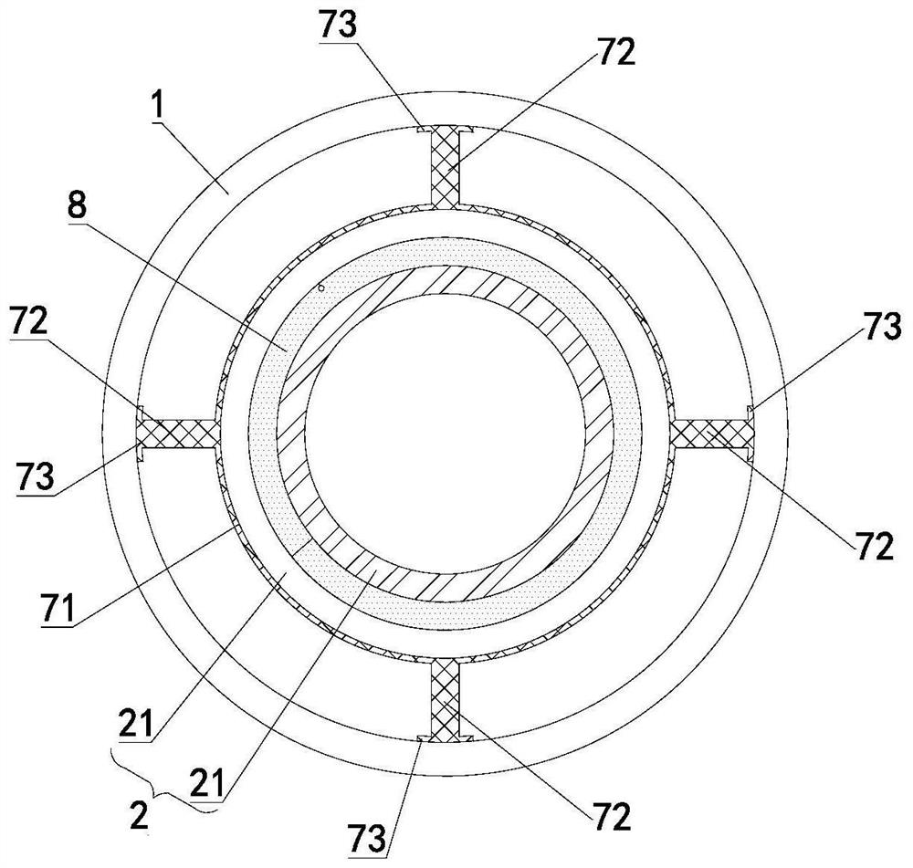
[0040] Such as Figure 1 ~ Figure 3As shown, a multi-chamber thermally insulated draft tube with a thermal insulation structure in this embodiment includes an outer tube 1 and an inner tube 2, the bottom of the outer tube 1 is a sealed structure, and the top and bottom of the inner tube 2 are both It is an open structure; a first cavity 3 is formed between the inner tube 2 and the outer tube 1, and the middle part of the inner tube 2 has a second cavity 4 axially penetrated, and the inner tube 2 is sleeved on the In the outer tube 1, a communication area 6 is reserved between the bottom of the inner tube 2 and the bottom of the outer tube 1, and the first cavity 3 communicates with the second cavity through the communication area 6. The body 4 is connected; a third cavity 5 is formed between the inner wall and the outer wall of the inner tube 2, and the third cavity 5 is a vacuum cavity, and an insulating material 8 is sealed in the third cavity 5.

[0041] Wherein, the therm...

Embodiment 2

[0054] A method for preparing a multi-cavity heat-insulated draft tube with a heat-insulating structure described in Example 1, comprising the following steps: setting two steel pipes 21 together to form a double-layer steel pipe, welding and sealing one end of the double-layer steel pipe, The cavity between the double-layer steel pipes is the third cavity 5; the thermal insulation material 8 is filled into the third cavity 5, and then the other end of the double-layer steel pipe is evacuated while welding, and after the welding is completed, a There is an inner tube 2 with a sealed vacuum cavity; the inner tube 2 is sheathed in the outer tube 1 , and a communication area 6 is reserved between the bottom of the inner tube 2 and the bottom of the outer tube 1 .

[0055] Specifically, one end of the double-layer steel pipe uses a steel plate of the same material, and the workpiece is melted by laser welding to form a specific molten pool, thereby forming a second cavity with a se...


PUM

PropertyMeasurementUnit
Thermal conductivityaaaaaaaaaa

Abstract

The invention relates to a multi-cavity heat insulation flow guide pipe with a heat insulation structure and a preparation method thereof, and belongs to the related technical field of heat insulation flow guide. The multi-cavity heat insulation flow guide pipe comprises an outer pipe and an inner pipe, the bottom of the outer pipe is of a sealed structure, and the top and the bottom of the inner pipe are of open structures; a first cavity is formed between the inner pipe and the outer pipe, the middle of the inner pipe is provided with an axially-through second cavity, the inner pipe is arranged in the outer pipe in a sleeved mode, a communication area is reserved between the bottom of the inner pipe and the bottom of the outer pipe, and the first cavity is communicated with the second cavity through the communication area; and a third cavity is formed between the inner side wall and the outer side wall of the inner pipe, the third cavity is a vacuum cavity, and a heat preservation material is sealed in the third cavity. The multi-cavity heat insulation flow guide pipe can be used for a medium-deep geothermal energy utilization system, the comprehensive utilization effects of small occupied area, low geothermal energy loss and zero influence on the ecological environment are achieved, the heating requirements of buildings and agriculture can be met without using high-grade energy for heat compensation, and the maximum utilization efficiency of geothermal energy is achieved.

Description

technical field [0001] The invention relates to the technical field related to heat insulation and flow diversion, in particular to a multi-cavity heat insulation flow diversion pipe with a heat insulation structure and a preparation method thereof. Background technique [0002] At present, conventional geothermal energy utilization generally adopts heat pump systems, which are divided into the following main methods: 1. Utilization of surface water sources, using surface water as a cold and heat source; 2. Utilization of soil sources, using soil energy storage as a cooling 3. Shallow ground energy utilization, a water source heat pump system that uses shallow groundwater as a cold and heat source. These three technical forms are basically shallow or surface ground energy utilization, combined with heat pump technology to form a new energy utilization system. [0003] The existing conventional geothermal energy utilization has the following disadvantages: 1. Utilization of ...

Claims


Application Information

Patent Timeline
IPC IPC(8): F16L9/14F16L59/02F16L59/065F24T10/17
CPCF16L9/14F16L59/028F16L59/065F24T10/17Y02E10/10
Inventor 张鸣
Owner 北京千城集成房屋有限公司
Why Eureka
Try Eureka