Oil-gas double-cooling motor
A technology of oil and gas, motor shaft, applied in the direction of electrical components, electromechanical devices, electric components, etc., can solve the problems of poor cooling effect of cooling oil, large motor current, reducing the cruising range of electric vehicles and the performance of the whole machine, etc., which is conducive to maintenance. Installation, the effect of ensuring the strength
- Summary
- Abstract
- Description
- Claims
- Application Information
AI Technical Summary
Problems solved by technology
Method used
Image
Examples
Embodiment 1
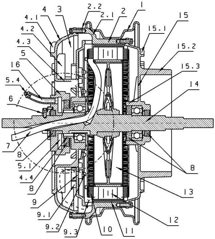
[0039] see Figure 1 to Figure 4 , Figure 9 , Figure 10 , Figure 18 ~ Figure 23 , an oil-air dual-cooled motor, including a motor shaft 14, a stator 12, a rotor 2 and a hub steel ring 1, the stator 12 is fixed on the motor shaft 14, the rotor 2 is sleeved on the stator 12, the outer ring of the rotor 2 and the hub steel ring 1 is welded and fixed, and the two ends of the rotor 2 are respectively fixed to the left end cover 4 of the motor and the right cover 15 of the motor; the key technology is that the rotor 2 is provided with a connecting ring 2.1, and the connecting ring 2.1 is provided with a support ring 2.2, and the support ring 2.2 is connected to the motor The left end cover 4 is connected, and the cooling liquid circulation cover 9 is fixedly installed on the right side of the left end cover 4 of the motor through the support column 4.6. A number of perfusion blocks 9.1 are arranged on the outer circumference of the cooling liquid circulation cover 9. An oil in...
Embodiment 2
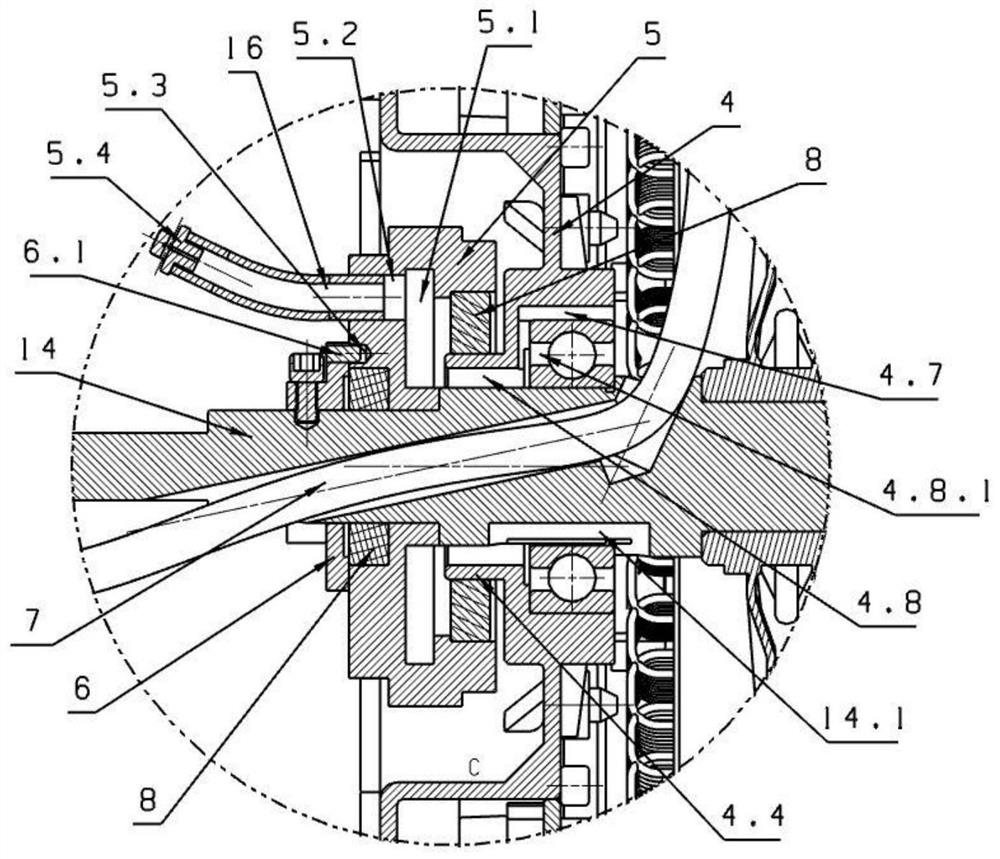
[0052] see Figure 5 ~ Figure 9 , Figure 18 ~ Figure 23 , the motor cooling oil heat dissipation circulation system and cooling oil separation system described in this embodiment are the same as those in Embodiment 1, and will not be repeated here. The difference lies in the pressure difference balance system inside and outside the motor cavity. An oil vapor recovery chamber 5 is installed in the concave cavity 4.3 outside the left end cover 4 of the motor to form a pressure difference balance system inside and outside the motor cavity. One end of the oil vapor recovery chamber 5 is set on the motor shaft 14 through the central shaft hole 5.5 and fixed by the positioning sleeve 6 , the oil vapor recovery chamber 5 is in a static state after being fixed by the positioning shaft sleeve 6, and the other end of the oil vapor recovery chamber 5 is set on the central shaft sleeve 4.4 of the left end cover 4 of the motor through an oil seal 8, and is opened at the circumferential po...
Embodiment 3
[0054] see Figure 11 , Figure 12 , Figure 15 ~ Figure 23 , the motor cooling oil cooling circulation system and cooling oil separation system described in this embodiment are the same as those in Embodiment 1, and will not be repeated here. The difference lies in the pressure difference balance system inside and outside the motor cavity. The pressure difference balance system inside and outside the motor cavity uses the extended section of the shaft sleeve of the left end cover 4 of the motor as the rotating oil vapor recovery chamber 4.9, so that the rotating oil vapor recovery chamber 4.9 and the left end cover 4 of the motor form a built-in integrated structure, and the rotating oil vapor recovery In the chamber 4.9, the flange 18 is fixedly installed by the positioning sleeve 6, and one or more ventilation holes 5.2 are arranged on the circumference of the flange 18, and waterproof and breathable valves 5.4 are respectively installed in the one or more ventilation hole...
PUM
 Abstract
Description
Claims
Application Information
 - R&D
- Intellectual Property
- Life Sciences
- Materials
- Tech Scout
- Unparalleled Data Quality
- Higher Quality Content
- 60% Fewer Hallucinations
Browse by: Latest US Patents, China's latest patents, Technical Efficacy Thesaurus, Application Domain, Technology Topic, Popular Technical Reports.
© 2025 PatSnap. All rights reserved.Legal|Privacy policy|Modern Slavery Act Transparency Statement|Sitemap|About US| Contact US: help@patsnap.com


