Optical system for forming point ring light spot
A technology of an optical system and an optical imaging system, which is applied in the field of optical systems for forming point-ring light spots, can solve the problems of complex processing of optical components, high price, and high system complexity, and achieves easy-to-change process requirements, reduced energy loss, and simple system. Effect
- Summary
- Abstract
- Description
- Claims
- Application Information
AI Technical Summary
Problems solved by technology
Method used
Image
Examples
Embodiment 1
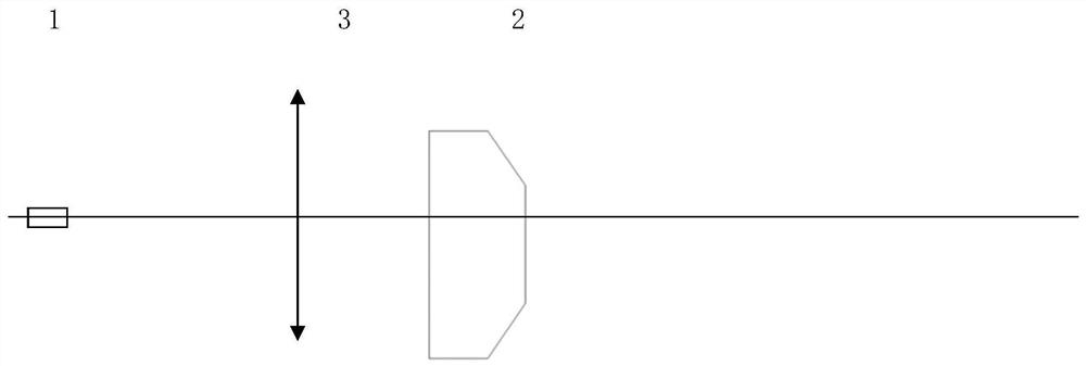
[0051] Example 1, in a specific usage scenario of the present invention, it is required to form a point ring-shaped spot structure: the central spot size is 50 microns, the ring-shaped spot diameter is 150 microns, the ring-shaped spot width is 50 microns, and the point spot energy is 60%. Ring spot power 40%. The input fiber core diameter is 25 microns and the numerical aperture is 0.06. According to this embodiment Figure 4 The shown structure designs a point ring spot optical system, wherein: the focal length of the collimator lens 3LC is 100 millimeters; the focal length of the focusing lens 3LF is 100 millimeters; 2 mm, the bottom diameter is 15 mm, and the effective clear aperture is 12 mm. According to the Gaussian distribution characteristics of the beam, the diameter of the top plane part of the frustum-shaped optical deflection element 2 is 6 mm, and the angle between the surrounding cone surface and the top plane is 0.093 degrees. . Through this optical system, ...
Embodiment 2
[0052] Embodiment 2, in another specific application scenario of the present invention, the structure required to form a point ring-shaped spot is: the size of the center spot is 100 microns, the diameter of the ring-shaped spot is 250 microns, the width of the ring-shaped spot is 50 microns, and the energy of the spot spot is 60% , ring spot power 40%. The input fiber core diameter is 25 microns and the numerical aperture is 0.06. According to this embodiment Figure 5 The shown structure design a point ring spot optical system, in which: the focal length of the collimator lens 3LC is 50 mm; the focal length of the focusing lens 3LF is 100 mm; 3 mm concave spherical surface, surrounded by parallel flat plates, the focal length of the central part is -6101.6 mm; the frustum-shaped optical deflection element 2 is made of quartz glass with a refractive index of 1.46, the height is 2 mm, the bottom is 8 mm, and the effective aperture is 6 mm. According to the Gaussian distribut...
Embodiment 3
[0053] Embodiment 3, in another specific application scenario of the present invention, the structure required to form a point ring-shaped spot is: the size of the central spot changes from 100 to 300 microns, correspondingly, the diameter of the ring-shaped spot changes from 200 to 600 microns, The ring spot width is changed from 50 microns to 150 microns, the point spot energy is 60%, and the ring spot energy is 40%. The input fiber core diameter is 25 microns and the numerical aperture is 0.06. According to this embodiment Figure 8The optical path shown is designed with a point ring spot optical system, in which: the focal length of the collimator lens 3LC is 50mm; The focal length of the lens 3LF1 is 541.6 millimeters, and the focal length of the second lens 3LF2 is 117.87 millimeters. Zooming is realized by adjusting the distance between the two lenses; Its focal length is minus 1073.6mm. The frustum-shaped optical deflection lens composite element 5 is made of quartz ...
PUM
| Property | Measurement | Unit |
|---|---|---|
| height | aaaaa | aaaaa |
| diameter | aaaaa | aaaaa |
| pore size | aaaaa | aaaaa |
Abstract
Description
Claims
Application Information
 - R&D
- Intellectual Property
- Life Sciences
- Materials
- Tech Scout
- Unparalleled Data Quality
- Higher Quality Content
- 60% Fewer Hallucinations
Browse by: Latest US Patents, China's latest patents, Technical Efficacy Thesaurus, Application Domain, Technology Topic, Popular Technical Reports.
© 2025 PatSnap. All rights reserved.Legal|Privacy policy|Modern Slavery Act Transparency Statement|Sitemap|About US| Contact US: help@patsnap.com


