
Novel laser electronic target

An electronic target and laser technology, which is applied to targets, target indication systems, attack equipment, etc., can solve the problems of inconvenient handling of electronic targets, heavy electronic targets, and inconvenience to carry, etc. cost, reduce complexity and maintenance difficulty

Pending Publication Date: 2021-12-21
JINAN ZHONGBANG ELECTRONICS +1
View PDF6 Cites 0 Cited by
  • Summary
  • Abstract
  • Description
  • Claims
  • Application Information

AI Technical Summary

Problems solved by technology

[0004] However, for the shooting area made of the light guide plate, in order to ensure the good transmission of light in the light guide plate, the light guide plate needs to have a certain thickness and good light transmittance. A certain thickness leads to the heavy weight of the electronic target, which is not easy to carry. Convenient, and the cost of materials with better light transmittance is generally higher
When the laser electronic target is used in the scene of education and teaching, the number of electronic targets required is large. If the electronic target is heavy, the handling of multiple electronic targets will be very inconvenient; and when it is popularized in education and teaching, the cost is high It is also difficult to be generally accepted by the electronic target

Method used


Image

  • Novel laser electronic target
  • Novel laser electronic target
  • Novel laser electronic target

Examples


example 1

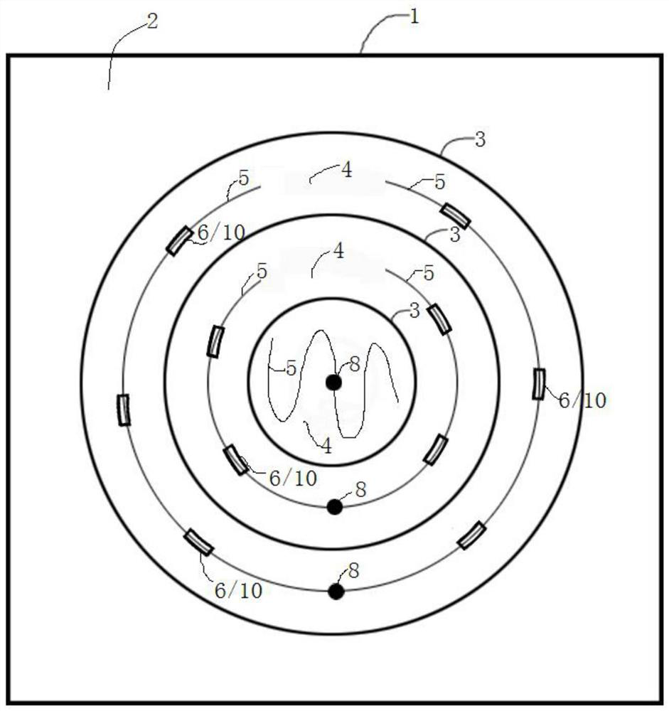
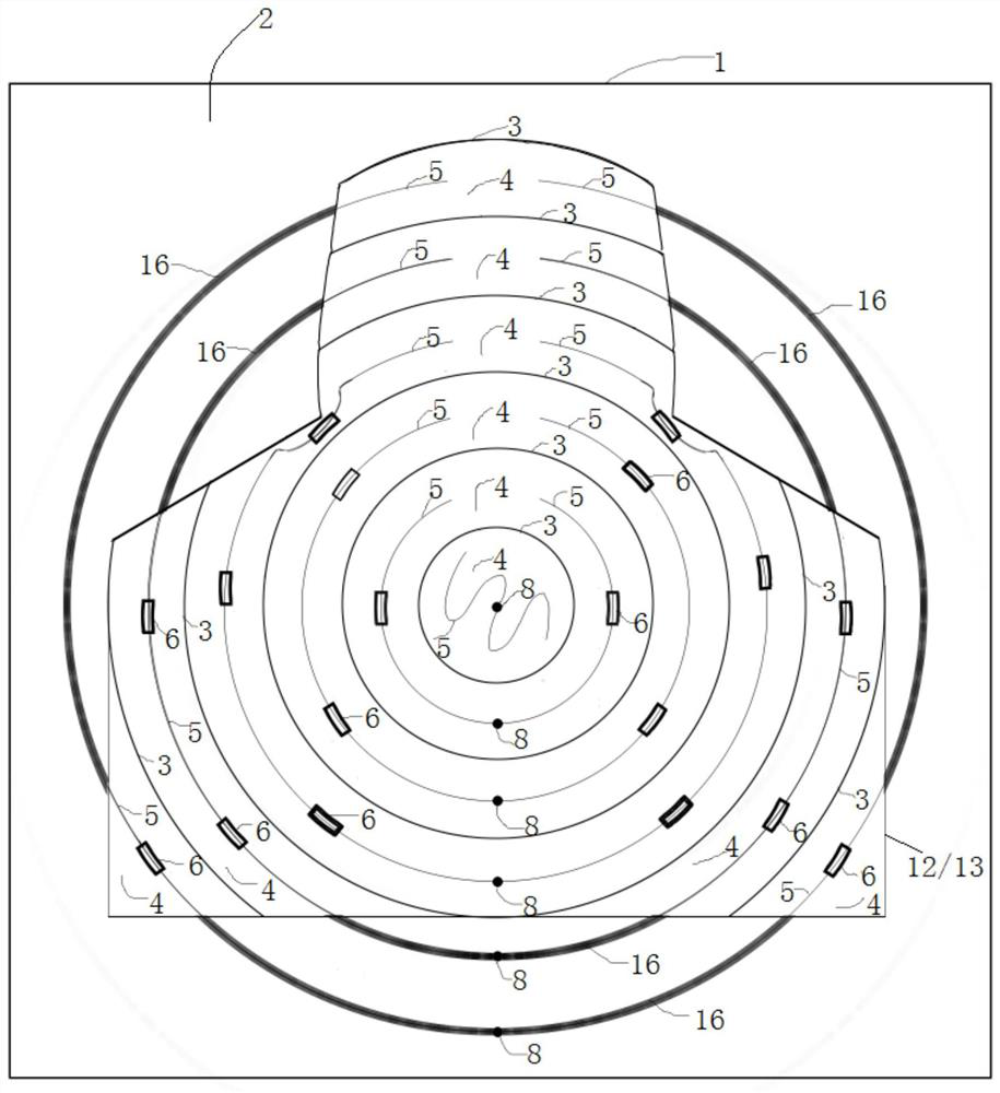
[0042] In this example, if Figure 1-4 As shown, the optical fiber 5 is a side-firing optical fiber, the side of the side-firing optical fiber is the light pickup surface 6 , and one or both end surfaces of the side-firing optical fiber are the light-emitting surface 7 .

[0043] Side-light optical fiber is also called full-body light-emitting optical fiber. It consists of a core material and a skin material. The refractive index of the core material is higher than that of the skin material. The core material is mostly made of transparent polymer or transparent organic matter. Vinyl fluoride, etc. Side-lit optical fibers are usually used for lighting and decoration. When in use, light is irradiated from one or both end faces of side-lit optical fibers and transmitted from the side, that is, through side-lit lighting. Since the light can enter from the end face of the side-light fiber and pass out from the side, then according to the reversible principle of the optical path, t...

example 2

[0047] In this example, if Figure 1-4 As shown, the optical fiber 5 is a side-light fiber, and a cut 9 is provided on the side-light fiber. The side of the side-light fiber and the cut surface at the cut are the light-picking surfaces, and one or both end faces of the side-light fiber are light-emitting surfaces.

[0048] In the foregoing example 1, the side surface of the side-firing optical fiber is used as the light-picking surface, which can achieve the purpose of picking up optical signals. However, after the laser beam is dispersed by diffuse reflection, its intensity will inevitably decrease, and although the side of the side-light fiber can also pick up light, the light-picking ability of the side-light fiber side is worse than that of its end face ( Not only side-lit optical fibers, but also other types of optical fibers have the strongest light-picking ability at the end face. For some types of optical fibers, the cortex is opaque, and the side does not have the lig...

example 3

[0057] In this example, the fiber is a side-light fiber, and a notch is opened on the side-light fiber. The side of the side-light fiber and the notch surface at the notch are the light-picking surfaces, and one or both end faces of the side-light fiber are light-emitting surfaces.

[0058] The difference between this example and Example 2 is that this example creates a notch on the side-light fiber, and the notch refers to cutting off a part of the side-light fiber by a cutter to form a V-shaped notch. Other parts are the same as Example 2, and will not be repeated in this example.


PUM


Abstract

The invention discloses a novel laser electronic target, and belongs to the field of simulation shooting. The novel laser electronic target comprises a bottom plate, the front surface of the bottom plate is a diffuse reflection reflective surface, multiple light blocking material strips protruding forwards are arranged on the front surface of the bottom plate, multiple shooting areas which do not communicate with one another are defined by the light blocking material strips, optical fibers are arranged in each shooting area, the optical fibers in each shooting area are provided with light pickup surfaces and light emitting surfaces, different numbers of light pickup surfaces are arranged according to the sizes of the shooting areas, it is ensured that light rays reflected by laser beams irradiating the diffuse reflection reflective surfaces can be picked up by the light pickup surfaces, the light emitting surfaces of the optical fibers in each shooting area are connected with a photoelectric sensor, and the photoelectric sensors are electrically connected to a processor. A light guide plate is not needed, the photoelectric sensors are reduced, the weight and cost of the laser electronic target can be greatly reduced, and the laser electronic target is convenient to use, maintain and popularize and apply in a large range.

Description

technical field [0001] The invention relates to the technical field of simulated shooting, in particular to a novel laser electronic target. Background technique [0002] The laser simulation shooting system is a realistic shooting training system built with high-tech means such as semiconductor laser technology, single-chip microcomputer technology, image processing technology, wireless communication technology, sensor technology, network technology, and database technology. [0003] When simulating shooting, after the laser hits the electronic target, it is necessary to judge the position (ring number, etc.) of the electronic target being hit. Chinese patent document CN204255183U discloses a laser electronic target and a target shooting system, which includes a plurality of shooting areas made of light guide plates, and each shooting area is provided with a photoelectric sensor. When the laser is irradiated on the shooting area, it spreads throughout the entire shooting a...

Claims


Application Information

Patent Timeline
IPC IPC(8): F41J5/02F41J1/01
CPCF41J5/02F41J1/01Y02E30/10
Inventor 李明李希萌刘勇于波李素梅张承斌李保国于春英赵艳平李娜
Owner JINAN ZHONGBANG ELECTRONICS
Learn More