Anti-pulling type rigidity-controllable piled raft foundation structure and construction method

A technology of piled raft foundation and stiffness, which is applied in the engineering practice of piled raft foundation with controllable stiffness. The problem of limited pullout resistance and loss of pullout resistance can be achieved to improve the anti-seepage ability, strong bonding ability and good corrosion resistance.

Active Publication Date: 2021-12-31
NANJING UNIV OF TECH
View PDF7 Cites 0 Cited by
  • Summary
  • Abstract
  • Description
  • Claims
  • Application Information

AI Technical Summary

Problems solved by technology

[0003] The disadvantage of the first point is that the foundation structure of piled rafts with controllable stiffness needs to be further optimized
[0004] The second disadvantage is that the pullout performance of the controlled stiffness piled raft foundation needs to be further optimized
The reason why the previous controllable stiffness pile raft foundation structure did not set uplift reinforcement is that if longitudinal pullout reinforcement is installed in the top structure of the controllable stiffness pile raft foundation, when the upper load gradually increases, the stiffness adjustment device will gradually produce compression deformation, As a result, the connected longitudinal steel bars are compressed and deformed, and then lose the pullout performance, resulting in the limited pullout performance of the joints of the existing controllable stiffness pile-raft foundation, which is not conducive to the further development of the controllable stiffness pile-raft foundation in super high-rise buildings. Promote application

Method used


Image

  • Anti-pulling type rigidity-controllable piled raft foundation structure and construction method
  • Anti-pulling type rigidity-controllable piled raft foundation structure and construction method
  • Anti-pulling type rigidity-controllable piled raft foundation structure and construction method

Examples


Embodiment 1

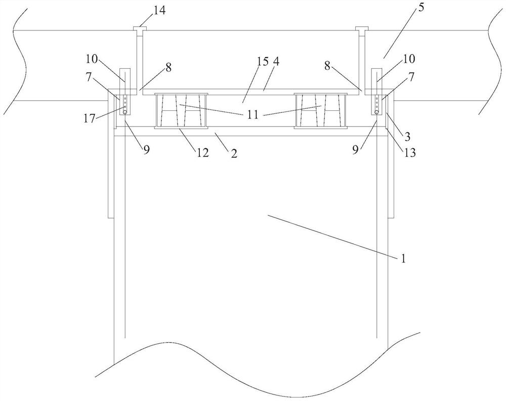
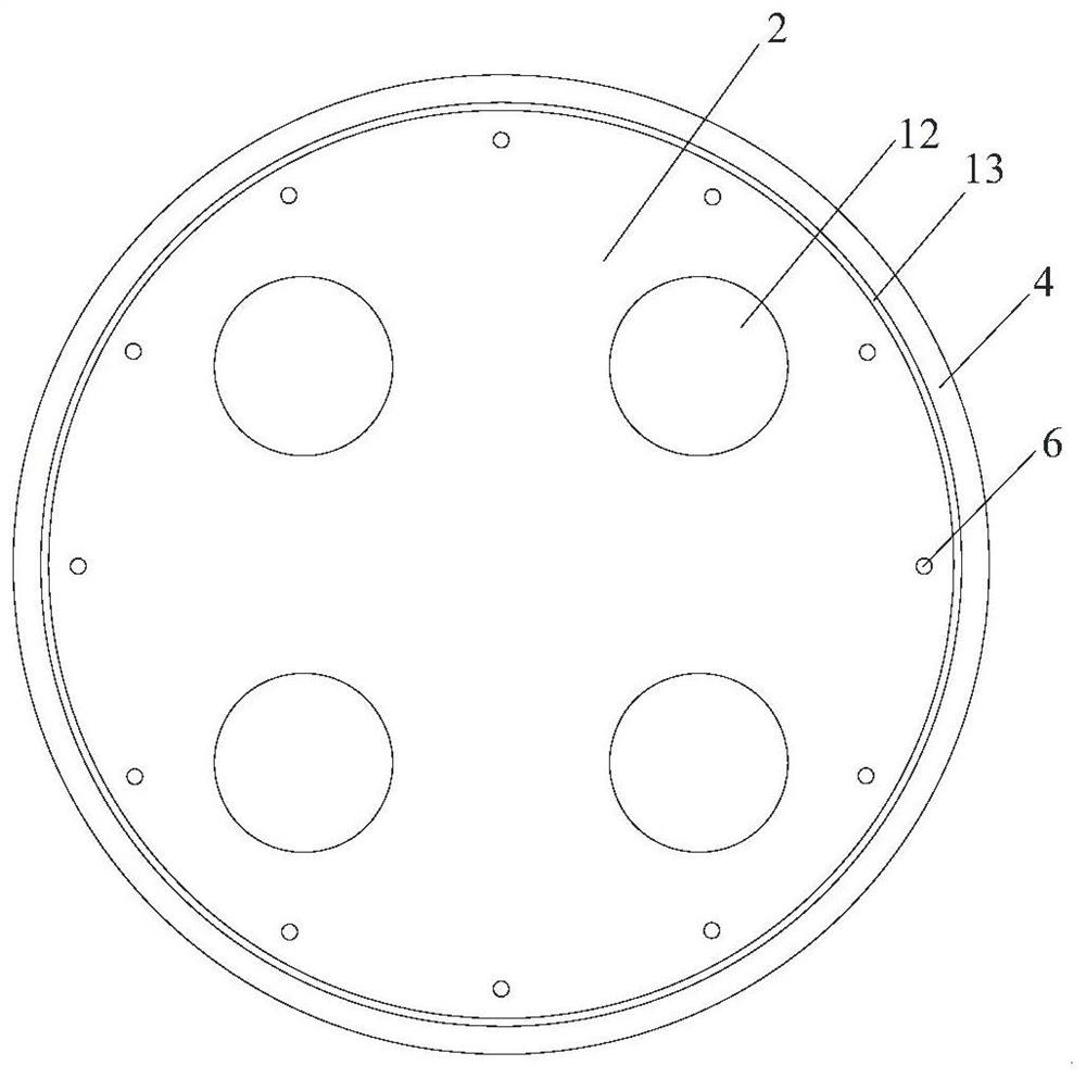
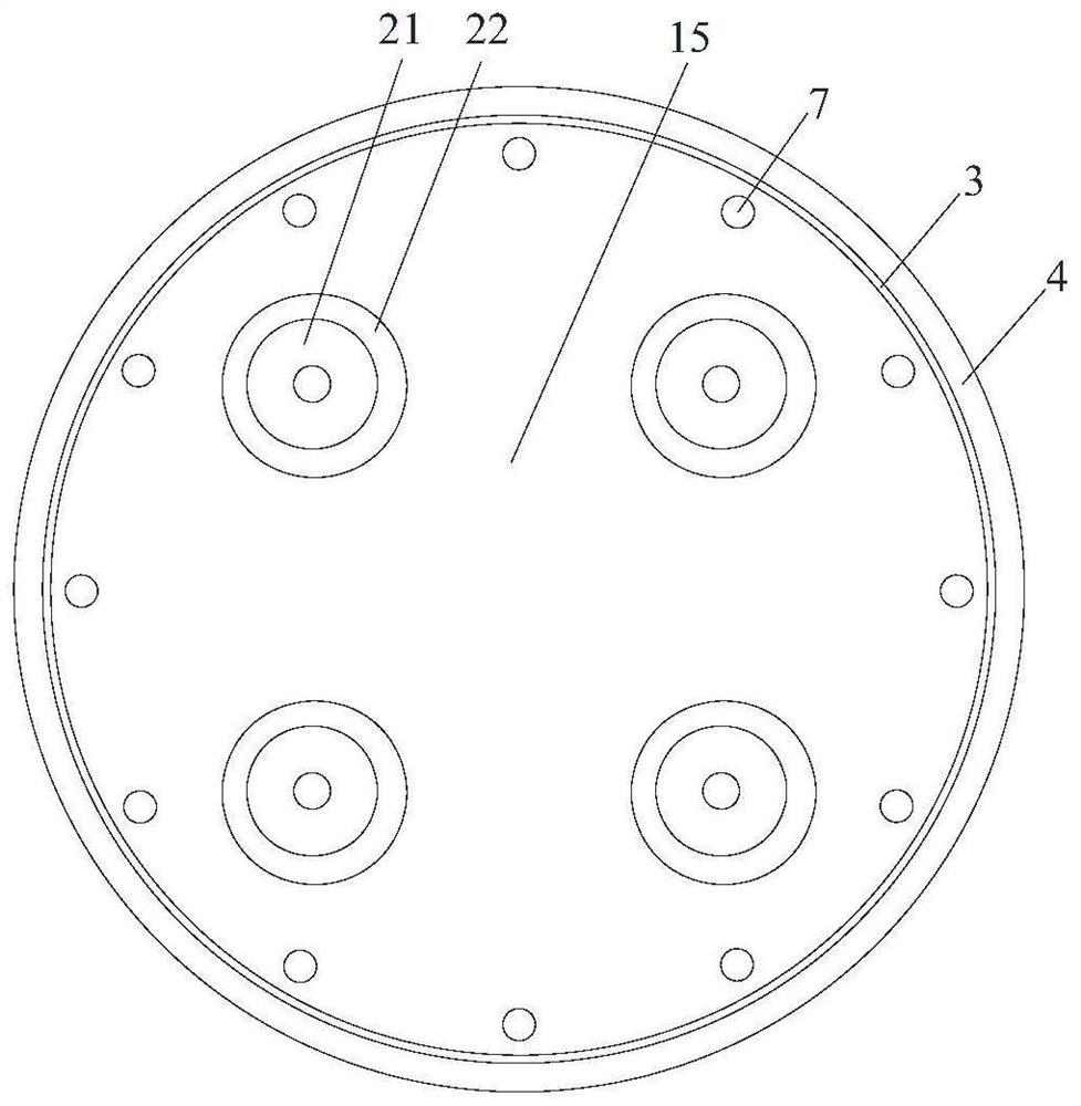
[0068] A controllable rigidity pile-raft foundation construction form of anti-pull and anti-seepage, such as figure 1 , figure 2 , image 3 As shown, it includes a base 2 fixedly installed on the top of the pile body 1, a flexible side guard plate 3, an integrated cylinder body 4, and a raft 5. The base 2 is fixedly installed on the top of the pile body 1, and the base 2 is provided with 12 A round hole 6, the bottom of the flexible side guard 3 is connected to the base 2, the integrated cylinder 4 is a circular structure with a closed top and an open bottom, and the inner wall of the top of the integrated cylinder 4 is provided with 12 A sleeve 7, a grouting hole 8, the lower part of the sleeve 7 is fixedly connected with the longitudinal reinforcement 9 in the pile body, and the steel bar 10 at the upper part of the sleeve is fixedly connected with the steel bar in the raft 5. The inner wall of the integrated cylinder 4 is fixedly connected with the outer wall of the flex...

Embodiment 2

[0099] The difference from Example 1 is that the grouting holes 8 are arranged on the same side, such as Image 6 shown.

Embodiment 3

[0101]The difference from Example 1 is that the cement-based high-strength grouting material is prepared from the following materials:

[0102] S1. Take the following raw materials and weigh them by weight: 110 parts of cement clinker, 11 parts of nano silicon oxide, 10 parts of steel fiber, 16 parts of ceramic particles, 22 parts of sodium silicate, 12 parts of slag, 20 parts of steel slag, aluminum oxide cooked 15 parts of raw materials, 20 parts of sodium nitrite, 10 parts of sodium stearate, 7 parts of phosphogypsum, 4 parts of titanium dioxide, 22 parts of river sand, 65 parts of sodium hydroxide, and 50 parts of industrial water glass;

[0103] S2. Add dry cement clinker, nano silicon oxide, steel fiber, sodium silicate, alumina clinker, sodium nitrite, sodium stearate, phosphogypsum and titanium dioxide into the pulverizer for grinding until the particle diameter is not larger than 0.1um, the mixed powder material A is obtained;

[0104] S3, adding the weighed sodium h...


PUM


Abstract

The invention discloses an anti-pulling type rigidity-controllable piled raft foundation structure and a construction method. The anti-pulling type rigidity-controllable piled raft foundation structure comprises a pile body, a raft plate, a base, side protection plates, a cylinder body and a rigidity adjusting device; the base at the top of the pile body is sleeved with the cylinder body; the inner side wall of the cylinder body is fixedly connected with the outer walls of the side protection plates and the pile body; the cylinder body is of a circular structure with the upper portion closed and the lower portion open; a plurality of sleeves and grouting holes are formed in the top of the cylinder body; the lower portions of the sleeves are fixedly connected with longitudinal bars in the pile body; the upper portions of the sleeves are connected with steel bars in the raft plate; and the grouting holes in the top of the cylinder body communicate with a grouting channel in the raft plate. According to the anti-pulling type rigidity-controllable piled raft foundation structure and the construction method, the sleeves are effectively utilized for being connected with the longitudinal bars of the pile body and the steel bars in the raft plate, and the anti-pulling performance of the joint of a rigidity-controllable piled raft foundation is greatly improved. The mode that the flexible side protection plates, the rigidity integrated cylinder body and the base are combined and connected through a cementing material is adopted, and the seepage-proofing capacity of the top structure of the pile body of the rigidity-controllable piled raft foundation is improved.

Description

technical field [0001] The invention belongs to the technical field of foundations, and relates to an uplift-resistant pile-raft foundation structure with controllable stiffness and a construction method, which are used for engineering practice of pile-raft foundations with controllable stiffness. Background technique [0002] Controllable stiffness piled raft foundation is a new type of piled raft foundation with a special stiffness adjustment device on the top of the pile body, which can effectively intervene and adjust the supporting stiffness of the pile foundation. By optimizing the deformation coordination between piles and piles and piles and soil, the controllable stiffness pile raft foundation can effectively solve the pile-soil interaction of large-supported stiffness piles such as end-bearing piles, especially rock-socketed piles, and the variable stiffness of large-chassis buildings or building groups. Leveling, complex geological conditions such as boulders, kar...

Claims


Application Information

Patent Timeline
Patent Type & Authority Applications(China)
IPC IPC(8): E02D27/01E02D5/34E02D31/00C04B28/26C04B111/70
CPCE02D27/01E02D5/34E02D31/00C04B28/26C04B2111/70C04B7/00C04B14/062C04B14/48C04B14/02C04B18/14C04B18/142C04B14/303C04B22/085C04B24/085C04B22/144C04B14/305C04B14/068C04B22/062
Inventor 周峰朱锐宋著王旭东
Owner NANJING UNIV OF TECH
Why Eureka
Try Eureka