Chemical tail gas treatment device with recovery function

A chemical exhaust gas treatment and function technology, applied in valve operation/release device, valve device, pump device, etc., can solve the problems of heat energy loss, waste, and the circuit switching is not uniform and smooth, and achieves the effect of avoiding loss

Active Publication Date: 2022-01-11
宁夏滨泽新能源科技有限公司
View PDF9 Cites 0 Cited by
  • Summary
  • Abstract
  • Description
  • Claims
  • Application Information

AI Technical Summary

Problems solved by technology

[0004] First, the interior of the incinerator is heated by the continuous jet flame of the burner. After the VOC in the exhaust gas is burned and decomposed, the hot gas generated still has a high temperature energy. The existing equipment is to transport and transfer the generated hot gas. For heat energy recovery and utilization, the process path of transportation and transfer is long, the heat energy will be further lost in the process, and there is a lot of waste. The existing equipment cannot directly use the heat energy after combustion
[0005] Second, after the tail gas enters the incinerator, the substances in it need to reach a certain temperature before they can be burned and decomposed. The lower the temperature of the tail gas before entering the incinerator, the longer it takes to be burned and decomposed in the incinerator, and the output from the incinerator The temperature is relatively constant, but the temperature of the exhaust fluctuates, which will affect the effect of combustion and decomposition
[0006] Third, when the regenerator inside the existing incinerator switches the air inlet and outlet, only a single compartment is gradually adjusted each time, and the circuit switching of the air inlet and outlet is not uniform and smooth, resulting in uneven inlet temperature.
[0007] Fourth, while the regenerator inside the incinerator circulates exhaust gas, dust will remain on the inner wall of the regenerator gap. The existing equipment needs to be equipped with a separate power cleaning device, which consumes a lot of energy
[0008] Fifth, while the burner is spraying flames into the incineration tank, it is necessary to ensure sufficient oxygen delivery, otherwise the flame will be reduced during combustion. The existing equipment only delivers oxygen through the flame injection pipeline of the burner, and there is insufficient oxygen delivery. risks of

Method used


Image

  • Chemical tail gas treatment device with recovery function
  • Chemical tail gas treatment device with recovery function
  • Chemical tail gas treatment device with recovery function

Examples


Embodiment 1

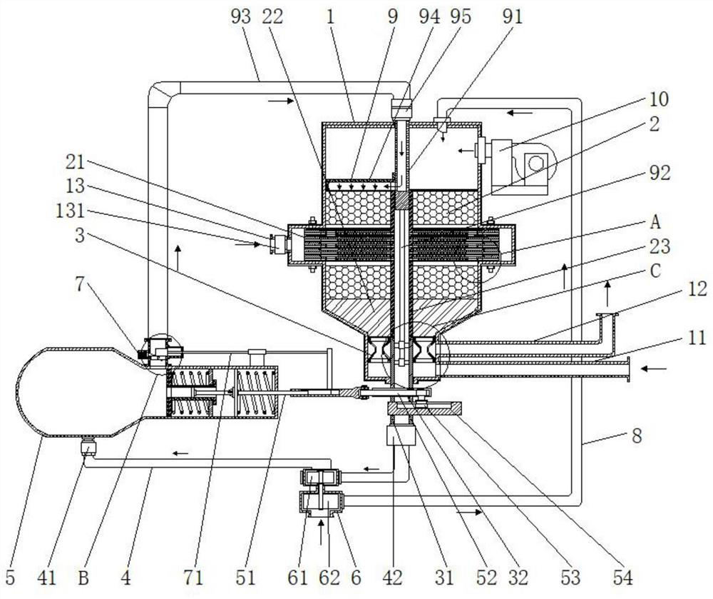
[0050] The present invention provides a kind of chemical tail gas treatment device with recovery function through improvement, such as Figure 1-Figure 16 As shown, a chemical tail gas treatment device with recovery function includes an incineration tank body 1, a burner 10 is connected to the top of one side of the incineration tank body 1, and a heat exchange combined heat storage body 2 is arranged inside the incineration tank body 1. The lower end of the heat exchange combined regenerator 2 is connected to one end of the steam transmission pipe 4 through the rotary valve assembly 3, the middle part of the steam transmission pipe 4 is connected to the oxygen booster pipe 8 through the turbocharger machine 6, and the steam transmission pipe 4 The other end is connected with a steam-powered push-pull tank 5, and one side of the steam-powered push-pull tank 5 is connected with an air jet cleaning assembly 9 through a passive pulse valve 7, and the air jet cleaning assembly 9 is...

Embodiment 2

[0061] The present invention provides a kind of chemical tail gas treatment device with recovery function through improvement, such as Figure 1-Figure 16 As shown, a chemical tail gas treatment device with recovery function includes an incineration tank body 1, a burner 10 is connected to the top of one side of the incineration tank body 1, and a heat exchange combined heat storage body 2 is arranged inside the incineration tank body 1. The lower end of the heat exchange combined regenerator 2 is connected to one end of the steam transmission pipe 4 through the rotary valve assembly 3, the middle part of the steam transmission pipe 4 is connected to the oxygen booster pipe 8 through the turbocharger machine 6, and the steam transmission pipe 4 The other end is connected with a steam-powered push-pull tank 5, and one side of the steam-powered push-pull tank 5 is connected with an air jet cleaning assembly 9 through a passive pulse valve 7, and the air jet cleaning assembly 9 is...


PUM


Abstract

The invention discloses a chemical tail gas treatment device with a recovery function. The device comprises an incineration tank body, wherein the top of one side of the incineration tank body is connected with a burner; a heat exchange combined heat accumulator is arranged in the incineration tank body; the lower end of the heat exchange combined heat accumulator is connected with one end of a steam transmission pipe through a rotary valve component; the other end of the steam transmission pipe is connected with a steam power push-pull tank; one side of the steam power push-pull tank is connected with an air injection cleaning component through a passive pulse valve; the air injection cleaning component is in linkage with the rotary valve component; and the rotary valve component and the passive pulse valve are both in linkage with the steam power push-pull tank. According to the chemical tail gas treatment device, the heat exchange combined heat accumulator is capable of simultaneously achieving heat accumulation and the heat exchange function, water liquid is heated through heat in the incineration tank body to generate steam, the action is directly conducted through the steam power push-pull tank, automatic air inlet and outlet switching and automatic air injection sweeping are achieved, the effect of directly recycling combustion heat energy is achieved, and the loss caused by heat energy transfer and retransportation is avoided.

Description

technical field [0001] The invention relates to the technical field of chemical tail gas treatment devices, in particular to a chemical tail gas treatment device with recovery function. Background technique [0002] Chemical tail gas refers to the poisonous and harmful gas discharged from chemical plants in chemical production. Chemical tail gas often contains many types of pollutants, complex physical and chemical properties, and different toxicity, which seriously pollutes the environment and affects human health. The composition of chemical tail gas produced by different chemical production industries varies greatly. For example, the tail gas produced by the chlor-alkali industry mainly contains chlorine, hydrogen chloride, vinyl chloride, mercury, acetylene, etc., and the tail gas produced by the nitrogen fertilizer industry mainly contains nitrogen oxides, urea dust, carbon monoxide, ammonia, sulfur dioxide, methane, etc. And automobile exhaust, etc.; for VOC tail gas...

Claims


Application Information

Patent Timeline
Patent Type & Authority Applications(China)
IPC IPC(8): F23G7/06F23G5/02F23G5/08F23G5/46F23G5/44F23J3/00F16K3/08F16K3/30F16K3/314F16K1/22F16K1/32F16K27/02F16K27/04F16K31/122F16K31/54F01D15/08F04D25/04
CPCF23G7/061F23G5/02F23G5/08F23G5/46F23G5/44F23J3/00F16K3/085F16K3/30F16K3/314F16K1/22F16K1/32F16K27/0218F16K27/045F16K31/1225F16K31/54F01D15/08F04D25/045F23G2204/10F23G2206/10F23G2209/14F23G2900/50213
Inventor 马骏
Owner 宁夏滨泽新能源科技有限公司
Why Eureka
Try Eureka