Beam splitting method and device for obtaining M*N beam laser array
A laser array and laser beam technology, applied in optics, optical components, instruments, etc., can solve problems such as complex optical path structure, large energy loss, and difficult adjustment of beam splitting ratio, and achieve the effect of simplifying the adjustment process and low energy loss
- Summary
- Abstract
- Description
- Claims
- Application Information
AI Technical Summary
Problems solved by technology
Method used
Image
Examples
Embodiment 1
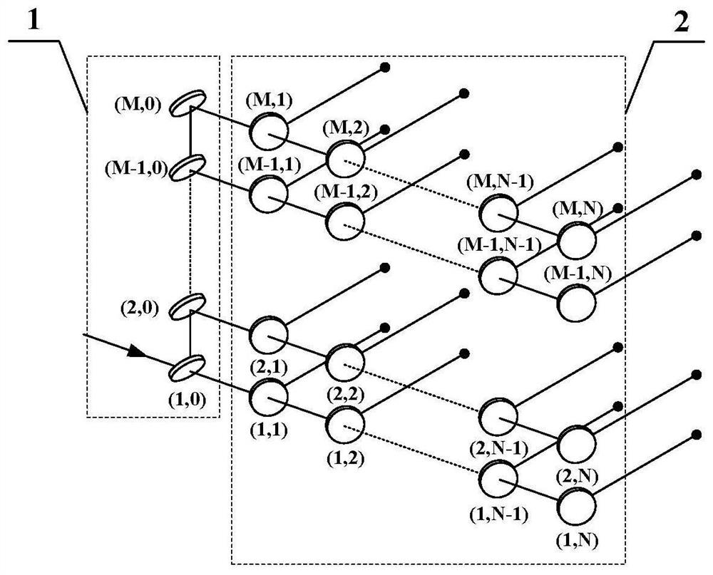
[0125] The beam splitting method used to obtain the M×N beam laser array is as follows figure 1 As shown, where M represents the number of laser array rows after longitudinal beam splitting, and N represents the number of laser beams in each row after horizontal beam splitting. Since the number of laser beams in each row can be different, record the number of beams in the mth row as N m , where m=1,2,...,M. The longitudinal beam splitting unit 1 is composed of beam splitting mirrors (1,0) to (M,0) arranged in the vertical direction, and the beam splitting mirrors form an included angle of 45° with the horizontal plane along the beam propagation direction. The incident laser beam enters the beam-splitting mirror (1,0) of the longitudinal beam-splitting unit 1 along the horizontal direction. Mirrors (2,0) to (M,0) are reflected to form the second to Mth laser beams, and each laser beam is still transmitted along the horizontal direction after longitudinal beam splitting. The t...
Embodiment 2
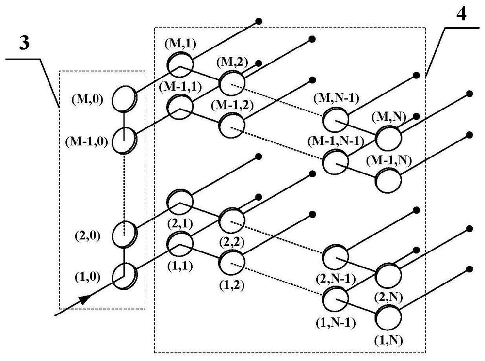
[0131] This embodiment is a further extension of Embodiment 1, such as figure 2 shown. Embodiment 2 is based on Embodiment 1, and adjusts the relative positions of the longitudinal beam splitting unit and the lateral beam splitting unit so that the propagation direction of the laser array after beam splitting is the same as that of the incident laser beam, thereby adapting to different application scenarios. figure 2 The longitudinal beamsplitter unit 3 in the figure 1 The longitudinal beam splitting unit 1 has the same structure, and the incident laser light to be split is divided into M beams in the vertical direction, output along the same direction, and enter the transverse beam splitting unit 4. The transverse beam splitting unit 4 has the same structure as the transverse beam splitting unit 2 . The longitudinal beam splitting unit 3 outputs the m-th row of laser beams, which are incident on the beam splitting mirror (m, 1) of the transverse beam splitting unit 4, and...
Embodiment 3
[0136] This embodiment is a further limitation of the specific embodiments 1 and 2. The beam splitting mirror is a parallel plane mirror. When the transmittance ratio is not zero, it is a 45° partial reflector; when the transmittance ratio is zero, it is a 45° total reflector. The incident surface of the 45° beam splitting mirror is coated with a partial reflection or total reflection film, and the transmittance ratio of the film layer follows the calculation result of the corresponding formula; the non-incident surface is coated with an anti-reflection film layer to avoid Fresnel reflection from affecting the actual beam splitting ratio The effect of beam interference on the cross-field distribution of the beam after beam splitting.
[0137] The absorption rate of the optical component material to the laser energy is lower than 1%, the diameter of the beam splitting mirror is greater than 1.5 times the diameter of the incident light, and the damage threshold should not be low...
PUM
 Abstract
Description
Claims
Application Information
 - R&D
- Intellectual Property
- Life Sciences
- Materials
- Tech Scout
- Unparalleled Data Quality
- Higher Quality Content
- 60% Fewer Hallucinations
Browse by: Latest US Patents, China's latest patents, Technical Efficacy Thesaurus, Application Domain, Technology Topic, Popular Technical Reports.
© 2025 PatSnap. All rights reserved.Legal|Privacy policy|Modern Slavery Act Transparency Statement|Sitemap|About US| Contact US: help@patsnap.com


