Direct-current micro-grid power transmission system applied to petroleum drilling machine

A DC micro-grid and power transmission system technology, which is applied to DC network circuit devices, parallel operation of DC power supplies, and conversion of irreversible AC power input into DC power output, etc. Improve efficiency and equipment service life, no need for treatment costs, and obvious energy-saving effects

Pending Publication Date: 2022-01-28
华兴智控(北京)能源有限公司
View PDF0 Cites 0 Cited by
  • Summary
  • Abstract
  • Description
  • Claims
  • Application Information

AI Technical Summary

Problems solved by technology

[0004] The purpose of the present invention is to provide a DC micro-grid power transmission system applied to oil drilling rigs, which solves the problem of AC harmonic pollution of the power plant on the well site, greatly improves the efficiency of the motor and the service life of the equipment, and the quality of the power grid is good without treatment costs; at the same time Configure the energy storage device to bear the impact load when the load changes suddenly, maintain the stability of the DC bus voltage, and ensure the normal operation of the system

Method used


Image

  • Direct-current micro-grid power transmission system applied to petroleum drilling machine
  • Direct-current micro-grid power transmission system applied to petroleum drilling machine

Examples


Embodiment 1

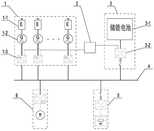
[0025] Such as figure 1 As shown, the permanent magnet synchronous generator set is equipped with a PWM rectification control device: the engine 1-1 rotates to drive the permanent magnet synchronous generator set 1-2 to generate alternating current, and then the PWM rectification control device 1-3 outputs direct current to the common DC bus 4 for energy storage The unit 3 is connected in parallel to the common DC bus 4 through the energy storage control device 3-2, and the common DC bus 4 provides DC power for the load unit 6 to drive the drilling equipment to run. The central controller 2 establishes communication with the PWM rectification control device 1-3 and the energy storage control device 3-2, and the common DC bus 4 provides DC power for the inverter controller of the load unit 6 to drive the load unit 6 to run; the braking unit 5 is Consume excess power on the bus when needed.

[0026] In order to realize the normal operation of the DC microgrid in both steady sta...

Embodiment 2

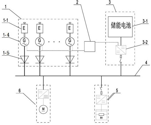
[0029] Such as figure 2 As shown, the 12-phase generator set 1-4 is equipped with a 24-pulse rectifier device 1-5. The 12-phase generator 1-4 and the 24-pulse rectifier device 1-5 are commercially available products, and will not be repeated here. The engine 1-1 drives the 12-phase generator 1-4 to run, and the 12-phase generator 1-4 sends out alternating current, which is rectified by the 24-pulse rectification device 1-5, and the output direct current is connected in parallel to the common direct current bus 4. The energy storage unit 3 is connected in parallel on the common DC bus 4, the central controller 2 establishes communication with each 12-phase generator and the energy storage control device 3-2, and the common DC bus 4 provides DC power for the load unit 6 inverter.

[0030] In order to realize the normal operation of the DC microgrid in both steady state and dynamic state, the central controller 2 coordinates the power generation unit and the energy storage unit ...


PUM


Abstract

The invention discloses a direct-current micro-grid power transmission system applied to a petroleum drilling machine. The system comprises a power generation rectification unit, a central controller, an energy storage unit, a common direct-current bus, a braking unit and a load unit; the power generation rectification unit is connected to a common direct current bus, the energy storage unit is connected to the common direct current bus, the control end of the central controller is connected with the controlled ends of the power generation rectification unit and the energy storage unit, and the brake unit and the load unit are connected to the common direct current bus in parallel; the system solves the problem of AC harmonic pollution of a well site power device, greatly improves the motor efficiency and the service life of equipment, is good in power grid quality, and does not need to treat cost; and meanwhile, an energy storage device is configured to bear an impact load when the load suddenly changes, maintain the DC bus voltage stable, and guarantee the normal operation of the system.

Description

technical field [0001] The invention relates to the technical field of oil drilling rig power transmission, in particular to a DC micro-grid power transmission system applied to oil drilling rigs. Background technique [0002] Most of the power sources of the traditional electronic control system of oil drilling rigs use 2-5 large-scale generator sets to be connected to the AC grid, or to obtain the required low-voltage AC power through a transformer on a special public grid line at the well site. According to different types of driving motors, it is divided into SCR system and VFD system. [0003] The SCR system obtains the power supply through the AC grid connection of the generator or the voltage transformation of the public grid, and uses a six-pulse wave controllable rectifier device (DC governor) to change the trigger angle of the thyristor to adjust the voltage and speed, one for one or one for two Driving the DC motor in this way has the problems of large harmonics ...

Claims


Application Information

Patent Timeline
Patent Type & Authority Applications(China)
IPC IPC(8): H02J1/10H02J1/14H02J1/16H02M7/04
CPCH02J1/10H02J1/106H02J1/109H02J1/14H02J1/16H02M7/04
Inventor 刘洁生秦胜利马李杰谢涛
Owner 华兴智控(北京)能源有限公司
Why Eureka
Try Eureka