Liquid organic hydrogen storage device and method

A hydrogen storage device and organic technology, applied in chemical instruments and methods, hydrogen, inorganic chemistry, etc., can solve the problems of affecting hydrogen storage efficiency, small contact area, high cost of use, etc., and achieve the effect of improving reaction efficiency and increasing contact area

Active Publication Date: 2022-02-08
SUZHOU JINHONG GAS CO LTD
View PDF5 Cites 1 Cited by
  • Summary
  • Abstract
  • Description
  • Claims
  • Application Information

AI Technical Summary

Problems solved by technology
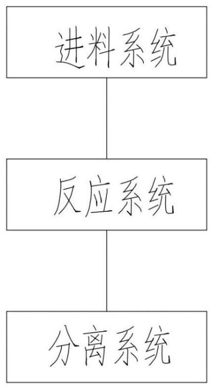
[0005] Patent No. CN105129728A introduces a hydrogen storage method using a reactor. This method is carried out in the reactor, and the reaction volume is limited by the volume of the reactor. It is only suitable for small laboratory tests and cannot be used for continuous hydrogen storage.
Patent No. CN109027683A introduces a hydrogen storage system and its control method. This method adopts a catalytic bed for catalytic hydrogenation, which requires a large amount of catalysts, and most of the hydrogen storage catalysts are noble metal catalysts, which are expensive to use.
For the trickle bed test device, when the granular catalyst is used for catalytic hydrogenation, the hydrogen storage material will flow down the tube wall, and the contact area is small, which seriously affects the hydrogen storage efficiency

Method used


Image

  • Liquid organic hydrogen storage device and method
  • Liquid organic hydrogen storage device and method
  • Liquid organic hydrogen storage device and method

Examples


specific example 1

[0060] Using benzyltoluene as hydrogen storage raw material:

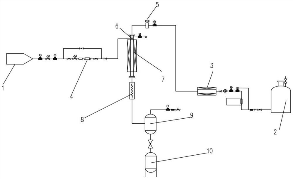
[0061] Step a: Before the reaction starts, use a helium leak detector to detect the pipeline, and to ensure that the pipeline is not leaking, use nitrogen to purge the entire pipeline so that there are no other impurity gases in the pipeline;

[0062] Step b: After the temperature is raised to 200°C, hydrogen gas is introduced. During the process of introducing hydrogen, the temperature will drop slightly. After the hydrogen pressure reaches 6MPa, keep it for a period of time to stabilize the temperature. At this time, the pressure range of the electromagnetic valve is set to 6.1-7.1 MPa, and the flow rate of benzyl toluene is set to 5 ml / min by the advection pump. When the temperature returns to the predetermined temperature, open the solenoid valve and the flow pump to feed;

[0063] Step c: After the solenoid valve receives the liquid pressure signal, it automatically opens the valve, and the liquid enters the...

specific example 2

[0066] Using dibenzyltoluene as hydrogen storage raw material:

[0067] Step a: Before the reaction starts, use a helium leak detector to detect the pipeline, and to ensure that the pipeline is not leaking, use nitrogen to purge the entire pipeline so that there are no other impurity gases in the pipeline;

[0068] Step b: After the temperature is raised to 200°C, hydrogen gas is introduced. During the process of introducing hydrogen, the temperature will drop slightly. After the hydrogen pressure reaches 7MPa, keep it for a period of time to stabilize the temperature. At this time, the pressure range of the electromagnetic valve is set to 7.1-8.1 MPa, and the flow rate of dibenzyltoluene is set to 2 ml / min by the advection pump. When the temperature returns to the predetermined temperature, open the solenoid valve and the flow pump to feed;

[0069] Step c: After the solenoid valve receives the liquid pressure signal, it automatically opens the valve, and the liquid enters ...


PUM

PropertyMeasurementUnit
lengthaaaaaaaaaa
particle diameteraaaaaaaaaa
widthaaaaaaaaaa

Abstract

The invention discloses a liquid organic hydrogen storage device, which comprises: a feeding system which is used for introducing gas and a hydrogen storage material; a reaction system which comprises an intermittent feeding reaction device and is used for carrying out hydrogenation reaction on the hydrogen storage material; and a separation system which is used for separating and collecting the hydrogenated hydrogen storage material and redundant hydrogen. According to the device disclosed by the invention, intermittent feeding is performed on a trickle bed in a manner of controlling the hydrogen storage material by an electromagnetic valve, so that the contact area of the material and a catalyst is increased, and the reaction efficiency is improved.

Description

technical field [0001] The invention relates to the technical field of hydrogen storage, in particular to a liquid organic hydrogen storage system and a batch feed reaction device. Background technique [0002] Hydrogen is widely used in large-scale industries for refining mineral oils, producing materials (e.g. steel, plastics, synthetic resins), bulk chemicals (e.g. ammonia, methanol) and fine chemicals. Most of the hydrogen used in these industrial processes needs to be at least 99.9% pure. Hydrogen is one of the most efficient energy carriers and can provide a stable power source for energy conversion. The safe and efficient use of hydrogen energy provides a means to address the urgent global greenhouse gas challenge. Central to the potential large-scale application of hydrogen technology in the market is the development of large-scale, high-density, and safe storage and transportation of hydrogen, which however remains one of the great challenges for today's technolog...

Claims


Application Information

Patent Timeline
Patent Type & Authority Applications(China)
IPC IPC(8): C01B3/00
CPCC01B3/0015C01B3/00Y02E60/32
Inventor 尹中南陈琪刘冬妮孙猛
Owner SUZHOU JINHONG GAS CO LTD
Why Eureka
Try Eureka