Electrostatic protection chip based on power management and preparation method thereof

An electrostatic protection and power management technology, applied in circuits, transistors, diodes, etc., can solve the problems of increasing device manufacturing costs, reducing device performance, and large device area, so as to improve withstand voltage performance, reduce leakage current, and fast response speed Effect

Pending Publication Date: 2022-02-08
深圳市鑫飞宏电子有限公司
0 Cites 0 Cited by

AI-Extracted Technical Summary

Problems solved by technology
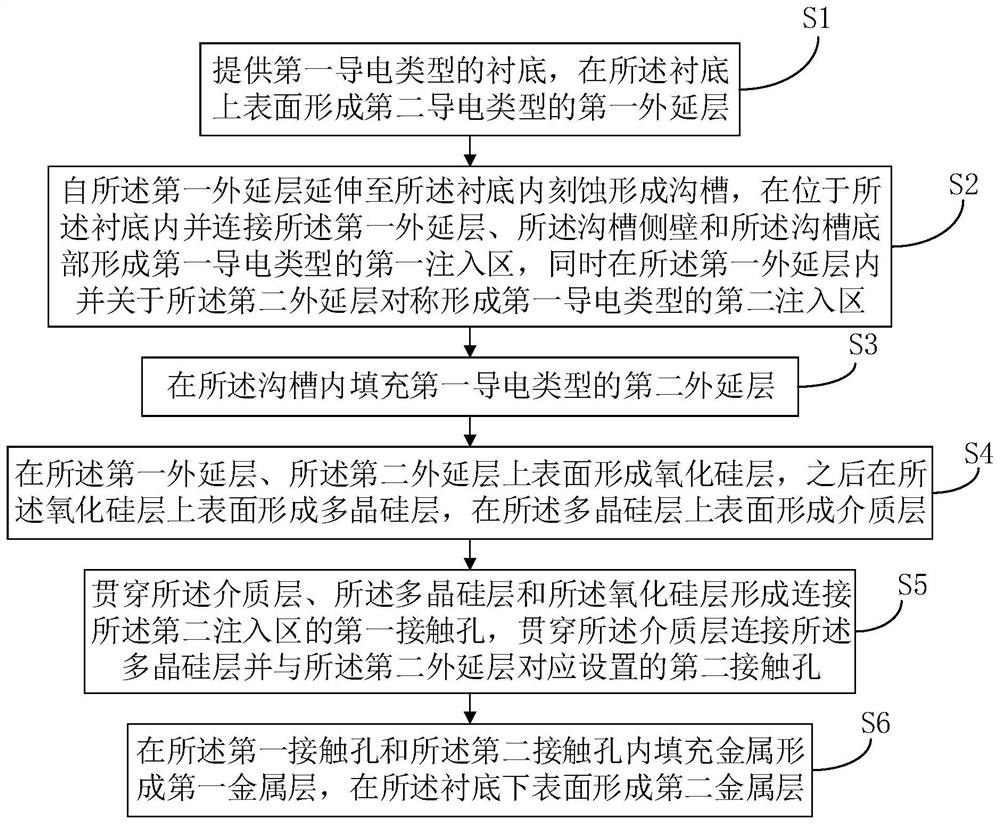
However, the additional capacitance introduced by these two structures is large, and the device area is...

Method used

In this embodiment, the first implanted region 23 and the second implanted region 24 are prepared by the same ion implantation, and the ion concentrations of the first implanted region 23 and the second implanted region 24 can be the same or different, silicon oxide Layer 25 can reduce leakage current in the device as an isolation layer, polysilicon layer 26 covers on silicon oxide layer 25 and can reduce semiconductor interface defects, and the first contact hole 28 and the second injection region 24 are connected to facilitate metal and second injection region 24 contact reduces on-resistance. The trench 21 extends from the first epitaxial layer 20 to the substrate 10 and fills the second epitaxial layer 22 in the trench 21, and is formed outside the trench 21, that is, the bottom of the trench 21 and the sidewall of the trench 21 located in the substrate 10 The ion concentration is higher than that of the first implantation region 23 of the substrate 10 to form a structure similar to the trench TVS, which improves the withstand voltage performance of the device to a certain extent. A conductive channel can be formed between the second injection region 24 , the first epitaxial layer 20 and the second epitaxial layer 22 , which reduces the parasitic capacitance inside the device. When a positive voltage is applied to the second metal layer 40, as the voltage increases, the negative pressure on the polysilicon layer 26 increases, and a P-type space charge region is induced in silicon oxide to ensure that the voltage on the polysilicon layer 26 is stable and can be turned on. The uniform channel improves the working stability of the device.
Referring to Fig. 2, in the present embodiment, the material of substrate 10 can be silicon or germanium, selects high-purity silicon as the material of substrate 10, is convenient to realize like this and can reduce manufacturing cost, and the first conductivity type is P-type , the second conductivity type is N type, and the resistivity of the first epitaxial layer 20 is 5-30 ohm/mm2. Epitaxial growth technology is used to form the first epitaxial layer 20. The epitaxial growth can be a homoepitaxial layer or a heterogeneous epitaxial layer. The substrate 10 is of the first conductivity type, that is, the P type, and the first epitaxial layer 20 is of the second conductivity type. That is, N-type, the first epitaxial layer 20 with a certain thickness can be obtained by low-pressure homoepitaxial growth, which is convenient for the subsequent preparation process.
Referring to Fig. 3, in the present embodiment, first on the first epitaxial layer 20, photoresist is coated at intervals, and the first epitaxial layer 20 not covered by photoresist is carried out photoetching to form groove 21, groove 21 extends from the upper surface of the first epitaxial layer 20 into the substrate 10, and then forms a U-shaped first implant region 23 on the bottom of the trench 21 and the side walls of the trench 21 in the substrate 10, and on the first epitaxial layer 20. P-type ion implantation is performed on the surface to form the second implantation region 24 . The first injection region 23 is formed by etching and has defects. The first injection region 23 is located in the substrate 10 connecting the sidewall of the trench 21, the bottom of the trench 21 and the first epitaxial layer 20, which can reduce the influence of defects on device performance. The second implantation region 24 is arranged symmetrically with respect to the trench 21 , and the first implantation region 23 is located outside the trench 21 , which is convenient for subsequent manufacturing to form a PNP structure. The conductivity type of the first injection region 23 and the second injection region 24 are the same as P type, the doping concentration of the first injection region 23 and the second injection region 24 can be the same, the first injection region 23 and the second injection region 24 The doping concentration can also be different, and the doping concentration of the first implantation region 23 and the second implantation region 24 is higher than that of the first epitaxial layer 20, which improves the working performance of the device.
Referring to Fig. 4, in the present embodiment, the width of trench 21 is greater than 2 μm, and second epitaxial layer 22 is formed by low-pressure epitaxial growth, and second epitaxial layer 22 is filled in trench 21, and second epitaxial layer 22 and first The implanted region 23 contacts, the doping concentration of the second epitaxial layer 22 is greater than the doping concentration of the first epitaxial layer 20, the doping concentration of the first implanted region 23 is greater than the doping concentration of the second epitaxial l...

Abstract

The invention discloses an electrostatic protection chip based on power management, which comprises a substrate, a first epitaxial layer formed on the substrate, a groove extending into the substrate from the first epitaxial layer, a second epitaxial layer filled in the groove, a first injection region which is positioned in the substrate and connected with the first epitaxial layer and the side wall and the bottom of the groove, second injection regions which are formed in the first epitaxial layer and arranged at intervals, a silicon oxide layer formed on the first epitaxial layer and the second epitaxial layer, a polycrystalline silicon layer formed on the silicon oxide layer, a dielectric layer on the polycrystalline silicon layer, a first contact hole which penetrates through the dielectric layer, the polycrystalline silicon layer and the silicon oxide layer and is connected with the second injection regions, a second contact hole which penetrates through the dielectric layer, is connected with the polycrystalline silicon layer and corresponds to the second epitaxial layer, a first metal layer which is formed on the dielectric layer and fills the first contact hole and the second contact hole, and a second metal layer formed on the lower surface of the substrate. The invention further provides a preparation method of the electrostatic protection chip based on power management, the parasitic capacitance is small, the response speed is high, the device area is small, and the working performance of the device is improved.

Application Domain

Technology Topic

Parasitic capacitorPolycrystalline silicon +6

Image

  • Electrostatic protection chip based on power management and preparation method thereof
  • Electrostatic protection chip based on power management and preparation method thereof
  • Electrostatic protection chip based on power management and preparation method thereof

Examples

  • Experimental program(1)

Example Embodiment

[0034] The following describes in detail the embodiments of the present invention, examples of which are illustrated in the accompanying drawings, wherein the same or similar reference numerals refer to the same or similar elements or elements having the same or similar functions throughout. The embodiments described below with reference to the accompanying drawings are exemplary, only used to explain the present invention, and should not be construed as a limitation of the present invention.
[0035] It should be noted that when an element is referred to as being "fixed to" another element, it can be directly on the other element or intervening elements may also be present. When an element is referred to as being "connected" to another element, it can be directly connected to the other element or intervening elements may also be present. In contrast, when an element is referred to as being "directly on" another element, there are no intervening elements present. The terms "vertical," "horizontal," "left," "right," and similar expressions are used herein for illustrative purposes only.
[0036] In the present invention, unless otherwise expressly specified and limited, terms such as "installation", "connection", "connection", "fixation" and other terms should be understood in a broad sense, for example, it may be a fixed connection or a detachable connection , or integrated; it can be a mechanical connection or an electrical connection; it can be a direct connection or an indirect connection through an intermediate medium, and it can be the internal communication between the two elements or the interaction relationship between the two elements. For those of ordinary skill in the art, the specific meanings of the above terms in the present invention can be understood according to specific situations.
[0037] see figure 1 , Figure 2 to Figure 6 , the present invention provides a preparation method of an electrostatic protection chip based on power management, comprising the following steps:
[0038] S1: providing a substrate 10 of a first conductivity type, and forming a first epitaxial layer 20 of a second conductivity type on the upper surface of the substrate 10;
[0039] see figure 2 In this embodiment, the material of the substrate 10 can be silicon or germanium, and high-purity silicon is selected as the material of the substrate 10, which is convenient for implementation and can reduce the manufacturing cost. The first conductivity type is P-type, and the second conductivity type is N type, the resistivity of the first epitaxial layer 20 is 5-30 ohm/mm 2. The first epitaxial layer 20 is formed by an epitaxial growth technique. The epitaxial growth can be a homo-epitaxial layer or a hetero-epitaxial layer. The substrate 10 is of the first conductivity type, namely the P-type, and the first epitaxial layer 20 is of the second conductivity type That is, the N-type, the first epitaxial layer 20 having a certain thickness can be obtained by using low-voltage homoepitaxy, which is convenient for the subsequent preparation process.
[0040]S2: extending from the first epitaxial layer 20 into the substrate 10 to form trenches 21 by etching, and connecting the first epitaxial layer 20 and the sidewalls of the trenches 21 in the substrate 10 forming a first implantation region 23 of a first conductivity type with the bottom of the trench 21, and forming a second implantation region 24 of the first conductivity type spaced in the first epitaxial layer 20 at the same time;
[0041] see image 3 In this embodiment, photoresist is firstly coated on the first epitaxial layer 20 at intervals, and the first epitaxial layer 20 not covered by the photoresist is subjected to photolithography to form a trench 21, and the trench 21 is formed from the first epitaxial layer. The upper surface of 20 extends into the substrate 10, and then a U-shaped first implantation region 23 is formed at the bottom of the trench 21 and the sidewall of the trench 21 in the substrate 10, and P-type ion implantation is performed on the upper surface of the first epitaxial layer 20. A second implant region 24 is formed. The first implanted region 23 is formed by etching and has defects. The first implanted region 23 is located in the substrate 10 and connects the sidewall of the trench 21, the bottom of the trench 21 and the first epitaxial layer 20, which can reduce the influence of defects on the device performance. The second implantation region 24 is symmetrically arranged with respect to the trench 21 , and the first implantation region 23 is located outside the trench 21 , which facilitates subsequent fabrication to form a PNP structure. The conductivity types of the first implantation region 23 and the second implantation region 24 are the same and both are P-type, and the doping concentration of the first implantation region 23 and the second implantation region 24 may be the same. The doping concentrations may also be different, and the doping concentrations of the first implantation region 23 and the second implantation region 24 are both greater than those of the first epitaxial layer 20, which improves the working performance of the device.
[0042] S3: filling the trench 21 with a second epitaxial layer 22 of the first conductivity type;
[0043] see Figure 4 In this embodiment, the width of the trench 21 is greater than 2 μm, the second epitaxial layer 22 is formed by low-pressure epitaxial growth, the trench 21 is filled with the second epitaxial layer 22, the second epitaxial layer 22 is in contact with the first implantation region 23, and the second epitaxial layer 22 is in contact with the first implantation region 23. The doping concentration of the second epitaxial layer 22 is greater than the doping concentration of the first epitaxial layer 20 , the doping concentration of the first implantation region 23 is greater than the doping concentration of the second epitaxial layer 22 , the second epitaxial layer 22 and the first epitaxial layer 20 A PN junction can be formed therebetween, a PN junction can be formed by contacting the first implanted region 23 with the first epitaxial layer 20, and a PNP structure can be formed by the second epitaxial layer 22, the first epitaxial layer 20 and the second implanted region 24, so that the response of the device The speed is fast, which can improve the work efficiency of power management.
[0044] S4 : forming a silicon oxide layer 25 on the upper surface of the first epitaxial layer 20 and the second epitaxial layer 22 , then forming a polysilicon layer 26 on the upper surface of the silicon oxide layer 25 , and forming a polysilicon layer 26 on the upper surface dielectric layer 27;
[0045] see Figure 5 In this embodiment, a layer of silicon oxide is deposited on the upper surfaces of the first epitaxial layer 20 and the second epitaxial layer 22 to form a silicon oxide layer 25, and the silicon oxide layer 25 covers the second implantation region 24 and the second epitaxial layer 22. Reduce interfacial stress. Then, a layer of polysilicon is deposited on the upper surface of the silicon oxide layer 25 to form a polysilicon layer 26, and a medium is grown on the upper surface of the polysilicon layer 26 to form a dielectric layer 27. Obtain a good interface state, which refers to some discrete or continuous electronic energy levels or energy bands at the silicon-silicon dioxide interface with energy values ​​located in the silicon forbidden band, which can be exchanged with the substrate semiconductor in a very short time The charge can ensure that the device responds quickly.
[0046] S5 : forming a first contact hole 28 connecting the second implantation region 24 through the dielectric layer 27 , the polysilicon layer 26 and the silicon oxide layer 25 , and connecting the polysilicon layer 26 and connecting the polysilicon layer 26 through the dielectric layer 27 . a second contact hole 29 corresponding to the second epitaxial layer 22;
[0047] see Image 6 In this embodiment, two first contact holes 28 and one second contact hole 29 are formed on the dielectric layer by photolithography. The first contact hole 28 is connected through the dielectric layer 27, the polysilicon layer 26 and the silicon oxide layer 25. To the second implantation region 24, the second contact hole 29 is connected to the polysilicon layer 26 through the dielectric layer 27 and is arranged corresponding to the second epitaxial layer 22. The junction depth of the first contact hole 28 is greater than that of the second contact hole 29, The first contact hole 28 and the second implantation region 24 are T-shaped, and the second contact hole 29 is connected to the polysilicon layer 26 and disposed correspondingly to the second epitaxial layer 22 , thereby improving the operational reliability of the device.
[0048] S6 : Fill metal in the first contact hole 28 and the second contact hole 29 to form a first metal layer 30 , and form a second metal layer 40 on the lower surface of the substrate 10 .
[0049] see again Image 6 In this embodiment, the first metal layer 30 is located in the two first contact holes 28, the second contact hole 29 and the upper surface of the dielectric layer 27, the second metal layer 40 is located on the lower surface of the substrate 10, and the two metal layers Can be used as two electrodes of the device. The magnetron sputtering technology is used on the first contact hole 28, the second contact hole 29 and the lower surface of the substrate 10, which needs to be filled with metal and then rapidly thermally annealed. The first metal layer 30 and the second metal layer 40 are simultaneously prepared by the same method. formed, and the preparation efficiency was improved.
[0050] It should be noted that the electrostatic protection chip 1 based on power management in this embodiment can be applied to an integrated electrostatic protection self-starting planar power MOS chip in a power management system. It combines the characteristics of VDMOS devices and trench TVS, and has With the features of small parasitic capacitance and low manufacturing cost, a new device structure is formed by the combination of the trench 21 and the implantation process. When a positive voltage is applied on the back of the device, that is, the second metal layer 40, when the voltage is low, the channel in the first epitaxial layer 20 from the second epitaxial layer 22 to the second implantation region 24 is not formed, and the current flows through the substrate 10, the first epitaxial layer 24 The P-N-P structure formed by the epitaxial layer 20 and the second implantation region 24 is turned on. The principle is similar to that of ordinary TVS. As the voltage increases, a P-type space charge region is induced on the lower surface of the silicon oxide layer 25 to form a P-type channel. , no longer through the PNP structure, the working principle is the same as that of the planar MOS. After the positive voltage applied by the second metal layer 40 exceeds the on-voltage drop of the second epitaxial layer 22 , the current passes through the substrate 10 , the first injection region 23 , the second epitaxial layer 22 , the first epitaxial layer 20 and the second injection The path formed by the region 24 can improve the response speed of the device without additionally increasing the area of ​​the device and reducing the manufacturing cost. The PNP structure turns on and discharges at low voltage, and the planar MOS structure turns on and discharges at high voltage, which greatly improves the device performance.
[0051] see Figure 7 , the present invention provides an electrostatic protection chip 1 based on power management, comprising:
[0052] a substrate 10 of the first conductivity type;
[0053] a first epitaxial layer 20 of the second conductivity type formed on the upper surface of the substrate 10;
[0054] The trench 21 extends from the first epitaxial layer 20 to the substrate 10 , the trench 21 is filled with a second epitaxial layer 22 of the first conductivity type, located in the substrate 10 and connected to all the the first epitaxial layer 20, the sidewalls of the trench 21 and the first implantation region 23 of the first conductivity type at the bottom of the trench 21;
[0055] a second implantation region 24 of the first conductivity type formed in the first epitaxial layer 20 and symmetrically arranged with respect to the second epitaxial layer 22;
[0056] A silicon oxide layer 25 formed on the upper surface of the first epitaxial layer 20 and the second epitaxial layer 22, a polysilicon layer 26 formed on the upper surface of the silicon oxide layer 25, and a dielectric layer formed on the upper surface of the polysilicon layer 26 27, penetrating the dielectric layer 27, the polysilicon layer 26 and the silicon oxide layer 25 and connecting the first contact hole 28 of the second implantation region 24, and connecting the polysilicon layer 26 and connecting the polysilicon layer 26 through the dielectric layer 27. a second contact hole 29 corresponding to the second epitaxial layer 22;
[0057] A first metal layer 30 formed on the dielectric layer 27 and filling the first contact hole 28 , the second contact hole 29 , and a second metal layer 40 formed on the lower surface of the substrate 10 .
[0058] In this embodiment, the first implantation region 23 and the second implantation region 24 are prepared by the same ion implantation. The ion concentration of the first implantation region 23 and the second implantation region 24 may be the same or different, and the silicon oxide layer 25 is used as the The isolation layer can reduce the leakage current in the device, the polysilicon layer 26 covering the silicon oxide layer 25 can reduce semiconductor interface defects, the connection between the first contact hole 28 and the second implantation region 24 is convenient to reduce the contact between the metal and the second implantation region 24 On resistance. The trench 21 extends from the first epitaxial layer 20 to the substrate 10 and the trench 21 is filled with the second epitaxial layer 22 . The ion concentration is higher than that of the first implanted region 23 of the substrate 10 to form a structure similar to the trench TVS, which improves the withstand voltage performance of the device to a certain extent. A conductive channel can be formed between the second implantation region 24 , the first epitaxial layer 20 and the second epitaxial layer 22 , thereby reducing the parasitic capacitance inside the device. When a positive voltage is applied to the second metal layer 40, as the voltage increases, the negative pressure on the polysilicon layer 26 increases, and a P-type space charge region is induced in the silicon oxide to ensure that the voltage on the polysilicon layer 26 is stable and can be turned on. The uniform channel improves the working stability of the device.
[0059] The present invention provides an electrostatic protection chip based on power management and a preparation method thereof. By forming a first epitaxial layer 20 on a substrate 10, a trench 21 is formed extending from the first epitaxial layer 20 into the substrate 10, and a groove 21 is formed on the substrate 10. The sidewalls of the trench 21 in the bottom 10 and the bottom of the trench 21 are connected to the first epitaxial layer 20 to form a first implantation region 23, and the trench 21 is filled with the second epitaxial layer 22, which can improve the withstand voltage performance of the device and reduce parasitic capacitance . The second implantation region 24 is symmetrically arranged with respect to the second epitaxial layer 22, and the silicon oxide layer 25 covers the second implantation region 24 and the second epitaxial layer 22, which can reduce the leakage current in the device. When a positive voltage is applied to the second metal layer 40, the region outside the trench 21 is turned on first, and as the voltage increases, the first implanted region 23 and the second epitaxial layer 22 in the trench 21 are turned on, and the second epitaxial layer is turned on. 22 can improve the withstand voltage performance of the device, and the first epitaxial layer 20 between the second epitaxial layer 22 and the second implantation region 24 forms a conductive channel, which makes the response speed of the device fast, replacing the ordinary trench used in power management. TVS devices and power MOSs do not increase the device area additionally, which improves the work efficiency of the power management system and reduces the device manufacturing cost.
[0060] In all examples shown and described herein, any specific value should be construed as merely exemplary and not as limiting, as other examples of exemplary embodiments may have different values.
[0061] It should be noted that like numerals and letters refer to like items in the following figures, so once an item is defined in one figure, it does not require further definition and explanation in subsequent figures.
[0062] The above-mentioned embodiments only represent several embodiments of the present invention, and the descriptions thereof are relatively specific and detailed, but should not be construed as limiting the scope of the present invention. It should be pointed out that for those of ordinary skill in the art, without departing from the concept of the present invention, several modifications and improvements can also be made, which all belong to the protection scope of the present invention.

PUM

no PUM

Description & Claims & Application Information

We can also present the details of the Description, Claims and Application information to help users get a comprehensive understanding of the technical details of the patent, such as background art, summary of invention, brief description of drawings, description of embodiments, and other original content. On the other hand, users can also determine the specific scope of protection of the technology through the list of claims; as well as understand the changes in the life cycle of the technology with the presentation of the patent timeline. Login to view more.

Similar technology patents

Classification and recommendation of technical efficacy words

  • Reduce leakage current
  • Improve pressure resistance

Medical Treatment System and Methods Using a Plurality of Fluid Lines

ActiveUS20160101227A1Reduce touchReduce leakage currentMedical devicesOptical detectionPeritoneal dialysisHemoperitoneum
Owner:DEKA PROD LLP

Methods and devices for leakage current reduction

ActiveUS20100308919A1Reduce leakage currentNegative-feedback-circuit arrangementsElectric pulse generator detailsLeakage current reductionDrain current
Owner:PSEMI CORP

Coriolis mass flowmeter

InactiveUS6895826B1Improve pressure resistancePrevent inertial momentDirect mass flowmetersEngineeringVibration sensor
Owner:OVAL CORP

Vacuum switch tube

Owner:BEIJING BOE VACUUM ELECTRONICS CO LTD
Why Eureka
Try Eureka