Plasma remelting system and process for thermal spraying of superfine powder

A technology of ultra-fine powder and plasma, applied in metal material coating process, coating, fusion spraying, etc., can solve the problems of easy decarburization of carbide powder, change of powder composition, change of powder particle size, etc., and achieve the best performance Effect

Pending Publication Date: 2022-02-25
中机凯博表面技术江苏有限公司
View PDF2 Cites 0 Cited by
  • Summary
  • Abstract
  • Description
  • Claims
  • Application Information

AI Technical Summary

Problems solved by technology

But for carbide powder, use the plasma remelting spheroidization process, the high temperature of the plasma will make the carbide powder easy to decarburize
The composition of the powder will change, and the hardness of the prepared coating will decrease
In additi

Method used


Image

  • Plasma remelting system and process for thermal spraying of superfine powder
  • Plasma remelting system and process for thermal spraying of superfine powder
  • Plasma remelting system and process for thermal spraying of superfine powder

Examples


Embodiment 1

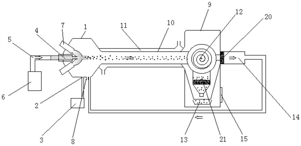
[0032] Embodiment 1: as figure 1As shown, a plasma remelting system for thermal spraying ultrafine powder includes a high-pressure chamber 1 in the remelting zone. The high-pressure chamber 1 in the remelting zone is provided with a vacuum port 2, and the vacuum port 2 communicates with the vacuum device 3. The high-pressure chamber 1 in the remelting zone is also provided with a feeding nozzle 4, and the feeding nozzle 4 is connected to the powder feeder 6 through the powder feeding pipe 5; the high-pressure chamber 1 in the remelting zone is also provided with more than two plasma torches 7, The plasma torch 7 and the high-pressure chamber 1 in the remelting zone are connected by a universal adjustment head, and the ejection outlet of the plasma torch 7 converges to the front end of the ejection outlet of the feeding nozzle 4; the high-pressure chamber 1 in the remelting zone is equipped with an inert The gas inlet 8, the high-pressure chamber 1 in the remelting zone are pro...

Embodiment 2

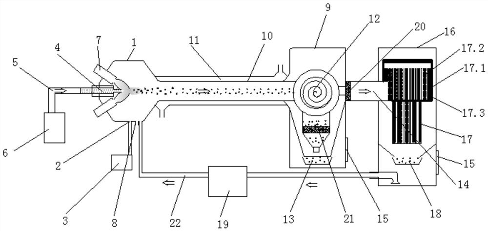
[0033] Embodiment 2: as figure 2 As shown, a plasma remelting system for thermal spraying ultrafine powder includes a high-pressure chamber 1 in the remelting zone. The high-pressure chamber 1 in the remelting zone is provided with a vacuum port 2, and the vacuum port 2 communicates with the vacuum device 3. The high-pressure chamber 1 in the remelting zone is also provided with a feeding nozzle 4, and the feeding nozzle 4 is connected to the powder feeder 6 through the powder feeding pipe 5; the high-pressure chamber 1 in the remelting zone is also provided with more than two plasma torches 7, The plasma torch 7 and the high-pressure chamber 1 in the remelting zone are connected by a universal adjustment head, and the ejection outlet of the plasma torch 7 converges to the front end of the ejection outlet of the feeding nozzle 4; the high-pressure chamber 1 in the remelting zone is equipped with an inert The gas inlet 8, the high-pressure chamber 1 in the remelting zone are p...

Embodiment 3

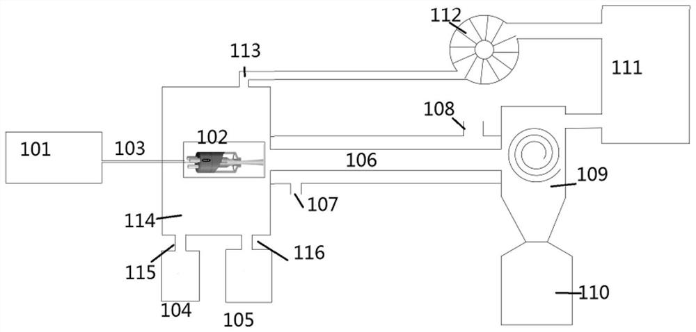
[0035] Embodiment 3: as image 3 , 4 As shown, 101 is a powder feeder, 102 is a plasma spray gun for thermal spraying, and 101 and 102 are connected through a powder feeding pipe 103 . 114 is a chamber, 104 is a vacuum device, connected with the chamber 114 through a valved pipeline 115, and 105 is a protective gas (such as nitrogen) bottle, connected with the chamber 114 through a valved pipeline 116; 106 is a cooling pipeline, on which Cooling water inlet 107 and water outlet 108 are provided; cyclone separator 109 is connected with cooling pipeline 106; cyclone separator 109 is connected with powder collector 110; air filter system 111 is connected with cyclone separator 109; fan 112 is connected with air filter system 111 is connected; fan 112 is connected with chamber 114 through pipeline 113 .

[0036] When working: the cooling water inlet 107 is fed with cooling water, the vacuum device 104 is turned on to pre-evacuate the inside of the plasma remelting spheroidizatio...


PUM


Abstract

A plasma remelting system for thermal spraying of superfine powder comprises a cavity, a powder feeder, a powder feeding pipe, a feeding nozzle, a plasma device, an inert gas circulation pipeline, a cooling pipeline, a cooling cavity wrapped outside the cooling pipeline and a powder collector; a vacuumizing connector is arranged on the cavity and is communicated with a vacuumizing device; and the feeding nozzle and the cooling pipeline are coaxially and horizontally arranged, the plasma device heats and remelts powder sprayed out of the feeding nozzle, and the powder is cooled in the cooling pipeline and finally collected by the powder collector. After powder particles rapidly absorb heat, the surfaces of the powder particles are molten, the powder particles are subjected to polycondensation under the action of surface tension to form spherical liquid drops, the spherical liquid drops enter the cooling pipeline and then are quenched and solidified to fix spheres, and thus the spherical powder high in surface density is obtained. The invention also relates to a process for remelting the superfine powder.

Description

technical field [0001] The invention relates to the field of thermal spraying, in particular to a plasma remelting system and process for thermal spraying superfine powder. Background technique [0002] Thermal spraying technology has received more and more attention in the field of surface strengthening technology. It melts the prepared powder or wire into droplets through a heat source, and sprays it onto the surface of the base material through a high-speed airflow to form a coating to improve the surface of the base material. Hardness, corrosion resistance, oxidation resistance, high temperature resistance and other properties. Therefore, it is widely used in aviation, aerospace, machinery, metallurgy and other fields. [0003] Thermal spraying powder accounts for more than 70% of the material in the thermal spraying process, and the particle size distribution, morphology and composition of powder particles will affect the coating effect. [0004] Tungsten carbide-base...

Claims


Application Information

Patent Timeline
IPC IPC(8): B22F9/14C23C4/06
CPCB22F9/14C23C4/06
Inventor 徐世霖哥兹·马特乌斯陈松
Owner 中机凯博表面技术江苏有限公司
Why Eureka
Try Eureka